Hydraulic lifting device

A technology of hydraulic lifting device and mounting frame, which is applied in the direction of inclined load-carrying vehicles, etc., which can solve the problems of time-consuming, laborious, and affecting vehicle passability, and achieve the effect of simple structure, easy maintenance and use

Inactive Publication Date: 2015-05-27
诸城市盛奥机械有限公司
View PDF0 Cites 0 Cited by
  • Summary
  • Abstract
  • Description
  • Claims
  • Application Information

AI Technical Summary

Problems solved by technology

[0002] At present, the power of the tricycle is intercepted and output from the rear side of the tricycle, and a mounting frame must be installed on the rear side. However, after adding the mounting frame, the frame body is too close to the ground, which affects the passability of the vehicle. It needs to be installed at the place of use, which is time-consuming , strenuous

Method used


Image

  • Hydraulic lifting device
  • Hydraulic lifting device

Examples


Embodiment Construction

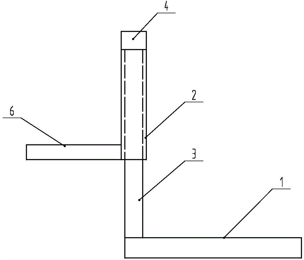
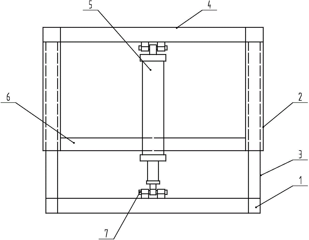
[0014] like figure 1 , 2 As shown, the present invention includes an agricultural machine frame, a guide pipe, a guide rod, a crossbeam, an oil cylinder, a mounting frame, and a pin shaft. , the top end of the guide pipe is connected by a crossbeam, an oil cylinder connected by a pin shaft is provided between the crossbeam and the agricultural machine frame, and a mounting frame is provided on the left side of the guide pipe.

[0015] Working principle of the present invention: installation frame is installed on the tricycle, the oil cylinder is connected with the oil pump of the tricycle, and the oil pump drives the oil cylinder, so that the agricultural machinery frame drives the guide rod to move up and down in the guide pipe.


PUM


Abstract

The invention discloses a hydraulic lifting device, which comprises an agricultural machine frame, guide tubes, guide rods, a beam, an oil cylinder, a mounting frame and pin shafts. The hydraulic lifting device is characterized in that the guide rods are arranged at the two ends of one side of the agricultural machine frame, and extend into the guide tubes, wherein the top ends of the guide tubes are connected through the beam; the oil cylinder connected through the pin shafts is arranged between the beam and the agricultural machine frame; the mounting frame is arranged on the left sides of the guide tubes. The hydraulic lifting device has the beneficial effects that the hydraulic lifting device can automatically ascend and descend, is raised when not being used, is lowered when being used, and can be upgraded for direct use.

Description

technical field [0001] The invention relates to a lifting device, in particular to a small agricultural lifting frame used on a tricycle. Background technique [0002] At present, the power of the tricycle is output from the rear of the tricycle after being intercepted, and a mounting frame must be installed on the rear side. However, after adding the mounting frame, the frame is too close to the ground, which affects the passability of the vehicle. It needs to be installed at the place of use, which is time-consuming , laborious. Contents of the invention [0003] The purpose of the present invention is to provide an upgrade device that can automatically lift, raise the height when not in use, and lower the height when in use, and can be used directly. [0004] In order to achieve the above object, the technical solution of the present invention includes an agricultural machine frame, a guide pipe, a guide rod, a beam, an oil cylinder, a mounting frame, and a pin shaft. ...

Claims


Application Information

Patent Timeline
IPC IPC(8): B60P1/16
Inventor 曲金明王钧如杨志勇
Owner 诸城市盛奥机械有限公司
Why Eureka
Try Eureka