Eureka AIR delivers breakthrough ideas for toughest innovation challenges, trusted by R&D personnel around the world.

Visual observation mechanism working in nuclear fusion chamber and control method thereof

A visual and working technology, which is applied in the field of visual observation mechanism and control, and can solve the problems of limited space detection range and positioning accuracy, and unstable operation.

Inactive Publication Date: 2015-05-20
HEFEI INSTITUTES OF PHYSICAL SCIENCE - CHINESE ACAD OF SCI
View PDF6 Cites 4 Cited by
  • Summary
  • Abstract
  • Description
  • Claims
  • Application Information

AI Technical Summary

Problems solved by technology

[0005] The present invention is to avoid the shortcomings of the above-mentioned prior art, and provides a visual observation mechanism and a control method working in the nuclear fusion cabin to overcome the interference caused by the cantilever scheme in the prior art. Due to defects such as limited space detection range and positioning accuracy and unstable operation, its motion trajectory can cover the large double ring channel at the bottom of the entire nuclear fusion cabin. The movement gait is similar to worm walking, with good operation stability and simple control. The pan / tilt realizes all-round visual information collection of three degrees of freedom in the interior space of the nuclear fusion cabin, in order to reduce the requirements on the carrying capacity of the robot walking mechanism body, and improve the movement of the nuclear environment remote control robot platform to the structured and specific environment inside the nuclear fusion cabin adaptability

Method used


Image

  • Visual observation mechanism working in nuclear fusion chamber and control method thereof
  • Visual observation mechanism working in nuclear fusion chamber and control method thereof
  • Visual observation mechanism working in nuclear fusion chamber and control method thereof

Examples


Embodiment Construction

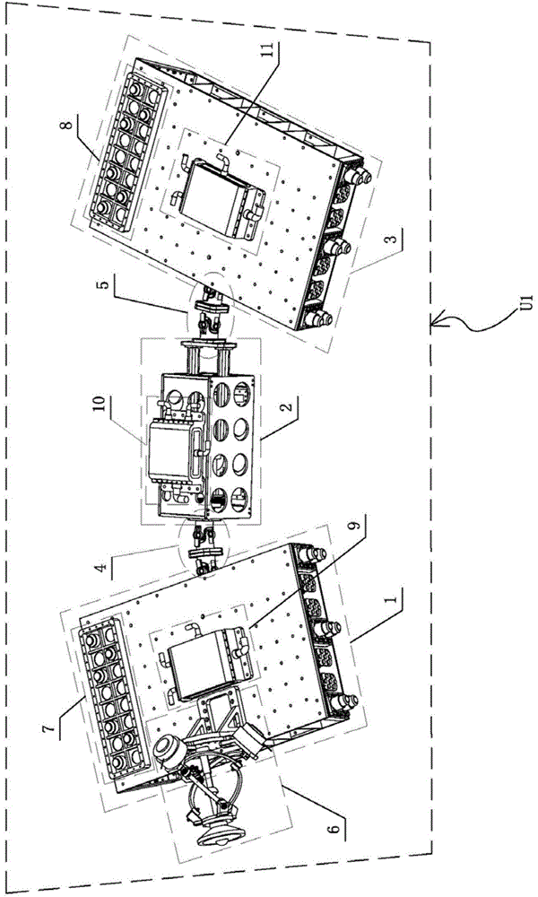
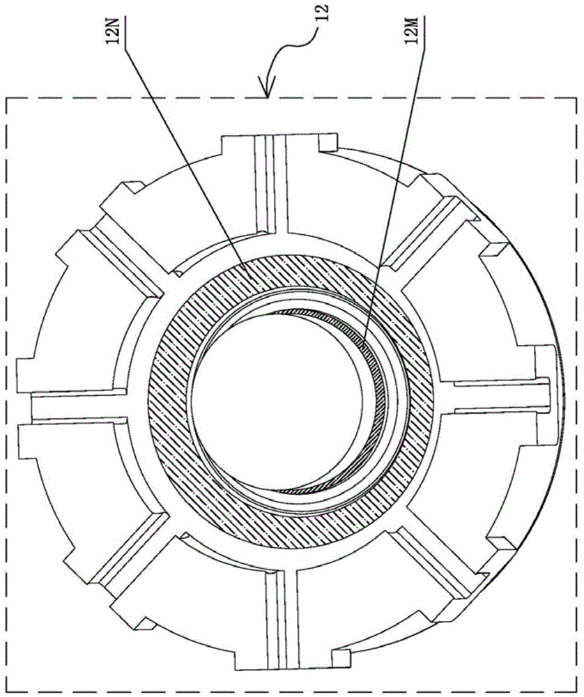
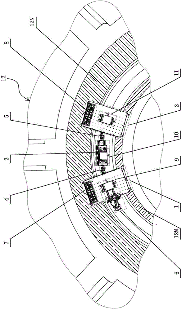
[0085] see figure 1 , figure 2 and image 3 , the structural form of the visual observation mechanism U1 working in the nuclear fusion cabin in this embodiment is: the front body segment lateral positioning module 1 and the rear body segment lateral positioning module 3 are two parts of the middle body segment axial movement module 2 End-symmetric setting constitutes the walking mechanism of the worm-like robot; Figure 4 As shown, the structure of the front body segment lateral positioning module 1 is as follows: the electric drive sub-module 1B is fixed inside the bearing sub-module 1A, and has the same structural form of the inner side split support sub-module 1C and the outer side split The support sub-module 1D is symmetrically arranged on the left and right sides of the electric drive sub-module 1B; one end of the inner side split support sub-module 1C and the outer side split support sub-module 1D are respectively fixedly connected to the left and right sides of the ...


PUM


Abstract

The invention discloses a visual observation mechanism working in a nuclear fusion chamber and a control method thereof. The visual observation mechanism is characterized in that a front body segment lateral positioning module and a rear body segment lateral positioning module are symmetrically arranged at two ends of a middle body segment axial motion module to form a traveling mechanism; a visual observation cloud deck is arranged at the front part of the front body segment lateral positioning module; the front body segment lateral positioning module and the middle body segment axial motion module are connected by a front double universal joint; the rear body segment lateral positioning module and the middle body segment axial motion module are connected by a rear double universal joint. According to the visual observation mechanism disclosed by the invention, the traveling mechanism is wide in motion range; the traveling track of the traveling mechanism can extend all over the complete cycle of a large-double circular channel at the bottom of the nuclear fusion chamber; the visual observation cloud deck is arranged in a matching way, so that all-round visual information acquisition of an annular space with a D-shaped section inside the nuclear fusion chamber can be finished.

Description

technical field [0001] The invention belongs to the field of nuclear environment remote control robot and automation technology, and more specifically relates to a visual observation mechanism and a control method working in a nuclear fusion cabin. Background technique [0002] Tokamak is a ring-shaped container that uses magnetic confinement to achieve controlled nuclear fusion. Its center is a ring-shaped vacuum chamber with a coil wound outside; when it is powered on, a huge spiral magnetic field will be generated inside the Tokamak, which will The plasma in it is heated to very high temperatures for the purpose of nuclear fusion. The internal cabin of a full tokamak device is generally called a nuclear fusion reaction cabin. As the core carrier of contemporary nuclear energy generation and preparation, its internal environment is a typical extreme environment. On the one hand, it has strong radiation, high temperature, strong magnetic field and high Physical characteris...

Claims


Application Information

Patent Timeline
Patent Type & Authority Applications(China)
IPC IPC(8): G21B1/25
CPCG21B1/25Y02E30/10
Inventor 张强闫清泉汪增福郑重乌达巴拉寇婕婷查正军
Owner HEFEI INSTITUTES OF PHYSICAL SCIENCE - CHINESE ACAD OF SCI
Why Eureka
Eureka Blog
Learn More