
Minitype concrete mixing machine

A concrete mixer, a small technology, is used in cement mixing devices, clay preparation devices, batching weighing instruments, etc., which can solve the problems of short service life of the mixing shaft, affecting the health of the builder, and high overall cost, and achieve the safety guarantee. Effect

Inactive Publication Date: 2015-05-20
JINLING INST OF TECH
View PDF4 Cites 11 Cited by
  • Summary
  • Abstract
  • Description
  • Claims
  • Application Information

AI Technical Summary

Problems solved by technology

[0002] Most of the concrete mixers currently on the market are large in size and heavy in weight. In order to ensure their stability during work, they are usually fixed on the ground at the construction site. The advantages of this type of large concrete mixer are large mixing volume and fast mixing speed. , but its disadvantage is that it is inconvenient to move and the overall cost is high, so it is only suitable for large construction sites
[0003] In order to solve the shortage of large concrete mixers, the industry has designed and produced a series of small concrete mixers. In the actual production and application process, it was found that the service life of the mixing shafts of such small concrete mixers is too short and easy to break; when feeding, dust If it rises, it will affect the health of the builder if it is inhaled; although it can be moved, it still needs to be fixed with the support device when it is placed, which is not practical; the stirring motor needs to be connected to the power supply, and when there is no power supply on the construction site , it cannot be used; feeding needs to manually weigh each component, and then put them into the mixing tank one by one, the work efficiency is slow

Method used


Image

  • Minitype concrete mixing machine
  • Minitype concrete mixing machine
  • Minitype concrete mixing machine

Examples


Embodiment Construction

[0014] Below in conjunction with accompanying drawing, the present invention is described in detail.

[0015] In order to make the object, technical solution and advantages of the present invention clearer, the present invention will be further described in detail below in conjunction with the accompanying drawings and specific embodiments. It should be understood that the specific embodiments described here are only used to explain the present invention, and are not intended to limit the present invention.

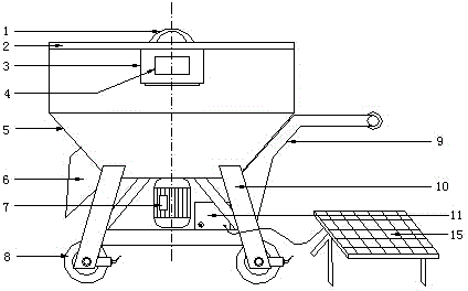
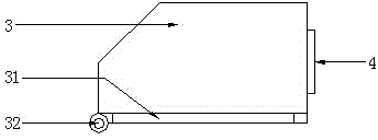
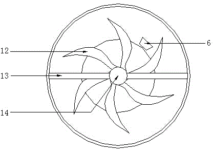
[0016] refer to figure 1 , the specific embodiment adopts the following technical solutions: it includes a handle 1, a bucket cover 2, a weighing feed hopper 3, a display 4, a mixing bucket 5, a discharge port 6, a stirring motor 7, casters with brakes 8, a push handle 9. Frame 10, battery 11, stirring blade 12, stirring shaft 14, casters 8 with brakes are installed on the lower end of the frame 10, push handle 9 is welded on one side of the frame 10, and the mixing ...


PUM


Abstract

The invention discloses a minitype concrete mixing machine, and relates to the technical field of construction equipment. Trundles with brakes are mounted at the lower ends of a rack; a push handle is welded on one side of the rack; a stirring barrel is mounted at the upper end of the rack and is fixedly welded with the push handle and the rack; a barrel cover is arranged at the upper end of the stirring barrel; a pull handle is mounted in the middle of the upper end of the barrel cover; a stirring shaft is vertically mounted inside the stirring barrel; the lower end of the stirring shaft penetrates out of the stirring barrel and is connected with a stirring motor positioned at the lower end of the stirring barrel; a plurality of stirring paddles are uniformly mounted on the outer wall of the stirring shaft; a weighing feeding hopper is hinged with one side of the upper end of the stirring barrel; a discharging hole is formed in one side of the lower end of the stirring barrel. The minitype concrete mixing machine is novel in design, simple in structure, relatively small in size, high in stability and high in practicability, and can conveniently move.

Description

technical field [0001] The invention relates to the technical field of construction equipment, in particular to a mixer, in particular to a small concrete mixer. Background technique [0002] Most of the concrete mixers currently on the market are large in size and heavy in weight. In order to ensure their stability during work, they are usually fixed on the ground at the construction site. The advantages of this type of large concrete mixer are large mixing volume and fast mixing speed. , but its disadvantage is that it is inconvenient to move and the overall cost is high, so it is only suitable for large construction sites. [0003] In order to solve the shortage of large concrete mixers, the industry has designed and produced a series of small concrete mixers. In the actual production and application process, it was found that the service life of the mixing shafts of such small concrete mixers is too short and easy to break; when feeding, dust If it rises, it will affec...

Claims


Application Information

Patent Timeline
Patent Type & Authority Applications(China)
IPC IPC(8): B28C5/16
CPCB28C5/16B28C5/0893B28C7/0445
Inventor 王书明王礼炜
Owner JINLING INST OF TECH
Learn More