Hydraulic power clamp

A hydraulic power and fixture technology, applied in the direction of clamping, clamping devices, manufacturing tools, etc., can solve the problems of high error of plate parts, low work efficiency, increased economic expenditure, etc., to improve processing efficiency and accuracy, High clamping and dismantling effect, and the effect of reducing economic expenditure

Inactive Publication Date: 2015-05-20
TAIZHOU VOCATIONAL & TECHN COLLEGE +1
View PDF5 Cites 1 Cited by
  • Summary
  • Abstract
  • Description
  • Claims
  • Application Information

AI Technical Summary

Problems solved by technology

The alignment is cumbersome, the clamping is not reliable, the rotating centrifugal force is large, and the efficiency of loading and unloading and aligning parts is low
In the process of drilling, turning, tapping, etc., the positioning is not reliable, and the parts may swing or rotate in the direction of rotation of the drilling or tapping, which will affect the drilling or tapping, and generally lead to a defective rate of processing. High, it may even cause the drill bit to be interrupted or pulled crookedly. In the high-speed machining environment, it is easy to cause damage to the CNC lathe spindle and other components, which will bring huge economic losses to the enterprise.
Usually, it takes time and energy to clamp and disassemble the processed parts. It is necessary to manually loosen the screws of the pressure plate and disassemble the clamping, which makes the work efficiency very low.
For plate parts of different sizes, it is necessary to customize different mounting seats and pressure plates, which increases the economic expenditure of the enterprise, and the waste of materials is also large. At the same time, the accuracy is extremely low, and the error of each plate part when processing the plate parts Extremely high

Method used


Image

  • Hydraulic power clamp
  • Hydraulic power clamp
  • Hydraulic power clamp

Examples


Embodiment Construction

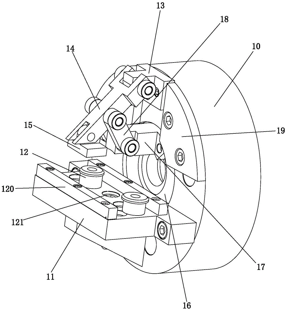
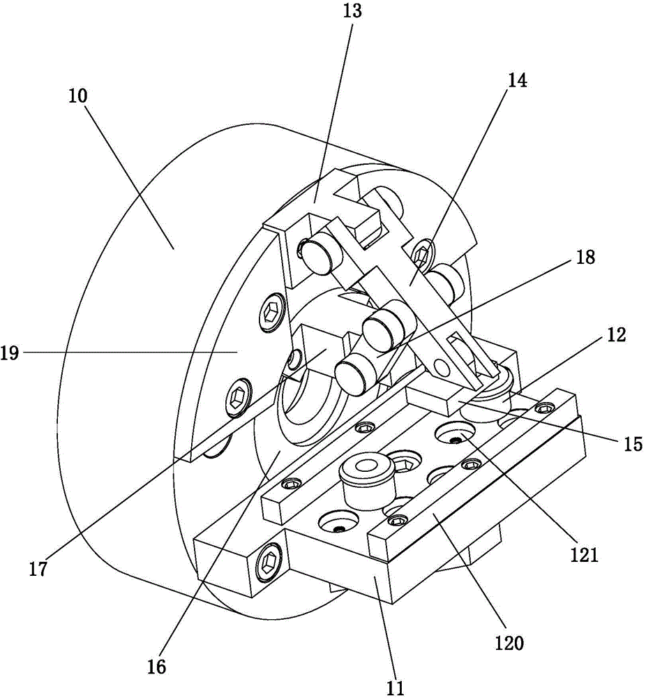
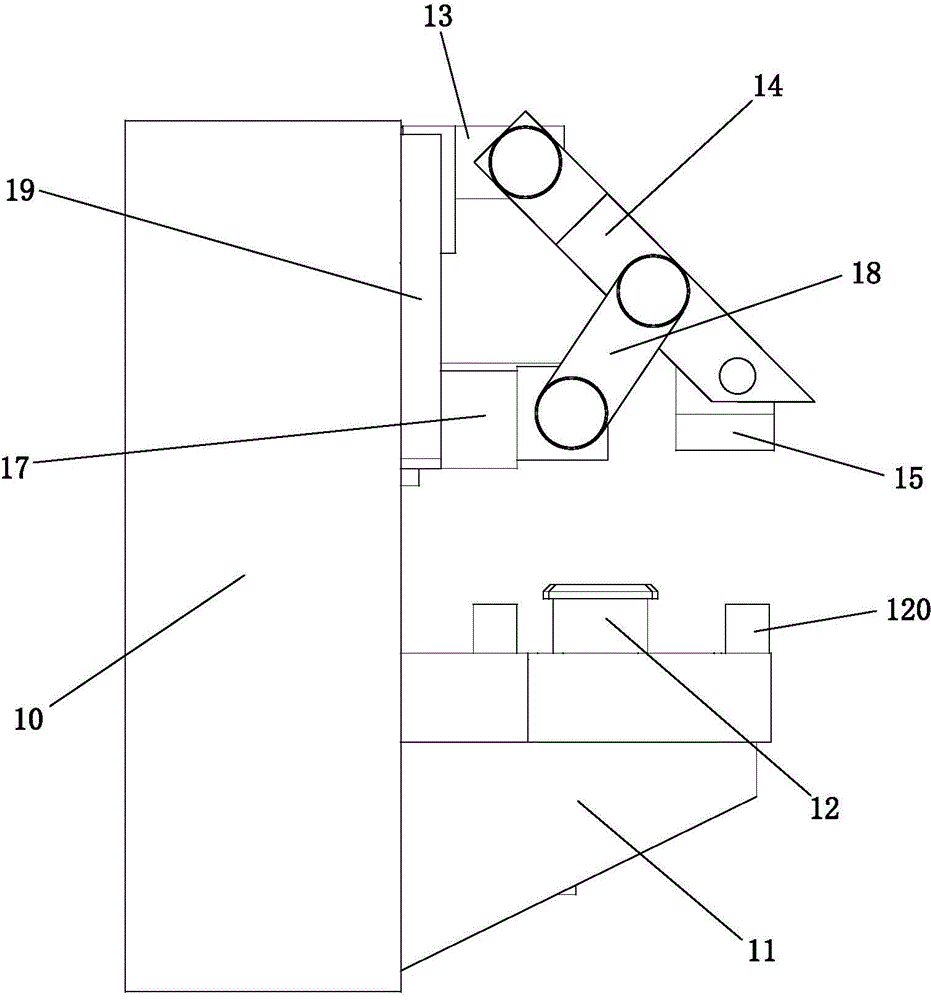
[0016] Such as Figure 1 to Figure 4 As shown, it is a hydraulic power clamp disclosed by the present invention, one side of the mounting base 10 is provided with a bent plate 11, and the side of the curved plate 11 perpendicular to the mounting base 10 is provided with replaceable two parallel clamps at intervals. The support block 120, the support block 120 is fixed on the bent plate 11 by means of screw fixing, of course, it can also be fixed by welding, or a positioning groove or a positioning hole is set at the position where the support block 120 is installed on the bent plate, The opposite surface of the support block 120 is provided with a positioning hole or a positioning groove matched with the positioning groove or the positioning hole for fixing, but for stability, the preferred screw fixing method, the replaceable setting of the support block 120 is mainly for convenience and adaptability. Different support blocks are selected for different workpieces to be proces...


PUM


Abstract

The invention relates to the technical field of clamping tools for digital controlled lathes, in particular to a hydraulic power clamp. A bending plate is arranged on one side of a mounting seat, the side surface of the bending plate, which is vertical to the mounting seat, is provided with two mutually parallel replaceable supporting blocks at intervals, a plurality of bolt fixing holes are formed in the bending plate between the two supporting blocks, positioning pins are inserted into two bolt fixing holes, one side of the mounting seat, which is opposite to the bending plate, is fixedly provided with a hinge joint seat, a connecting arm is hinged to the hinge joint seat, an extruding block which is matched with the two supporting blocks to clamp a to-be-machined part is hinged to the other end of the connecting arm, a guide hole which is located between the hinge joint seat and the bending plate is designed in the mounting seat, a guide sleeve is arranged in the guide hole in a sliding mode, a fixed support is fixedly disposed on the guide sleeve, and the middle of the connecting arm is connected with the fixed support through a connecting device. The hydraulic power clamp has the advantages that machining stability can be guaranteed, rapid clamping can be achieved, the clamping accuracy is extremely high, and machining efficiency and accuracy can be improved.

Description

technical field [0001] The invention relates to the technical field of clamping tools for numerically controlled lathes, in particular to a hydraulic power clamp. Background technique [0002] At present, the fixtures commonly used for clamping cuboid parts and irregularly shaped parts on CNC lathes are mostly four-jaw chucks, faceplates and bent plates. The structure is relatively simple, which has become a common recognition in the industry. This clamping method first needs to align the parts through the tedious dial gauge process, and then press it with a pressure plate, and then perform drilling, turning, tapping and other processing content. For single piece or small batch production, this clamping method is commonly used. The alignment is cumbersome, the clamping is not reliable, the rotating centrifugal force is large, and the efficiency of loading, unloading and aligning parts is low. In the process of drilling, turning, tapping, etc., the positioning is not reliab...

Claims


Application Information

Patent Timeline
Patent Type & Authority Applications(China)
IPC IPC(8): B23Q3/00
CPCB23Q3/12B23Q2703/04
Inventor 杨建西张健赵浩永
Owner TAIZHOU VOCATIONAL & TECHN COLLEGE
Why Eureka
Try Eureka