
Reactive power flow optimization method based on AVC system

An optimization method and power flow technology, applied in the directions of reactive power compensation, reactive power adjustment/elimination/compensation, AC network circuits, etc., can solve the problem that SVC cannot be coordinated, the economics of power grid operation is deteriorated, and voltage margin and voltage cannot be considered. deviations, etc.

Inactive Publication Date: 2015-05-13
STATE GRID CORP OF CHINA +2
View PDF5 Cites 6 Cited by
  • Summary
  • Abstract
  • Description
  • Claims
  • Application Information

AI Technical Summary

Problems solved by technology

[0003] 1) The traditional AVC uses the network loss as the target and the power flow, voltage and reactive power as the constraints to solve the solution, which can achieve better economy, but it cannot consider the voltage margin and voltage deviation, which makes the voltage deviation larger, that is The voltage will be adjusted in a large range, but due to economic considerations and neglect of safety, the voltage margin is not high, which brings potential safety hazards to the power grid, often outweighing the gains.
[0004] 2) The economy of power grid operation is an important indicator. Traditional AVC does not consider the changes brought about by the change of operation mode to the economy of power grid operation. The reason is that this problem is a problem that needs to be solved for the economic operation of transformers. AVC and transformer economic operation It is not isolated, there is coupling between them, looking at the economical operation of the transformer and AVC in isolation, it will make the economical efficiency of the power grid operation worse
[0005] 3) As an important reactive power equipment, SVC is widely used in the power grid. SVC is usually controlled independently and adjusted according to the established voltage and reactive power requirements, which makes it impossible for SVC to coordinate with other compensation equipment in the station.

Method used


Image

  • Reactive power flow optimization method based on AVC system
  • Reactive power flow optimization method based on AVC system
  • Reactive power flow optimization method based on AVC system

Examples


Embodiment Construction

[0049] A reactive power flow optimization method based on AVC system, comprising the following steps

[0050] (1) Establish a mathematical model with the system's active power loss, voltage stability margin, and voltage offset as the objective function, while considering the economy, fully guarantee the voltage stability margin and reduce the voltage offset;

[0051] (2), setting constraints including equality constraints and inequality constraints;

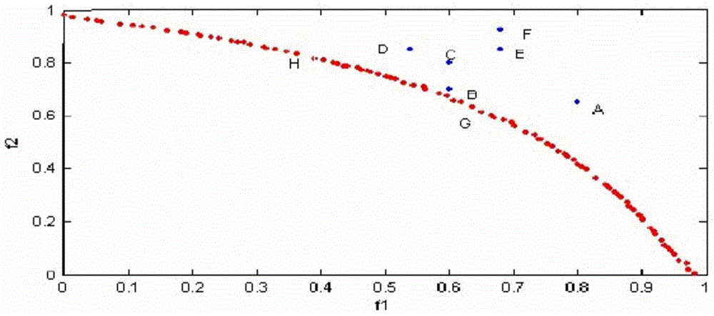
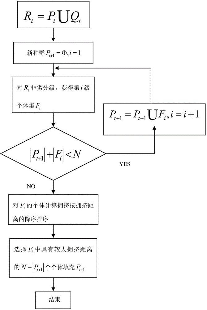
[0052] (3) Using the NSGA-II algorithm to solve the objective function, so that the running results converge on the global optimal solution;

[0053] (4) Formulate a control strategy according to the optimal solution of the objective function.

[0054] 1. Objective function

[0055] The objective function of power system reactive power flow optimization generally includes technical objectives and economic objectives. Among them, the economic goal mainly includes the minimum active power loss of the system; the technical goal i...


PUM


Abstract

A reactive power flow optimization method based on an AVC system includes the following steps: (1) building a mathematical model with active loss, voltage stability margin and voltage excursion of the system as a target function to fully guarantee the voltage stability margin and reduce voltage excursion while considering the economy; (2) setting constraint conditions including equality constraint and inequality constraints; (3) adopting an NSGA-II algorithm to solve a target function to enable an operation result to be converged on the global optimal solution; (4) making a control strategy according to the optimal solution of the target function. The method has good safety, economy and high adaptability.

Description

technical field [0001] The invention relates to a reactive power flow optimization method based on an AVC system. Background technique [0002] There are several technical problems in adopting traditional AVC: [0003] 1) The traditional AVC uses the network loss as the target and the power flow, voltage and reactive power as the constraints to solve the solution, which can achieve better economy, but it cannot consider the voltage margin and voltage deviation, which makes the voltage deviation larger, that is The voltage will be adjusted in a large range, but due to the consideration of economy and neglect of safety, the voltage margin is not high, which brings potential safety hazards to the power grid, and the gains outweigh the losses. [0004] 2) The economy of power grid operation is an important indicator. Traditional AVC does not consider the changes brought about by the change of operation mode to the economy of power grid operation. The reason is that this problem...

Claims


Application Information

Patent Timeline
IPC IPC(8): H02J3/18
CPCH02J3/16H02J2203/20Y02E40/30
Inventor 林纲朱宗毅王璘郭建钊苏家祥吴灿雄施蔚锦庄丽蓉黄晓东黄健苹洪志明
Owner STATE GRID CORP OF CHINA
Learn More