
Ball valve and air conditioner

An air conditioner and ball valve technology, applied in the field of ball valves and air conditioners with the ball valve, can solve the problems of improper protection of sealing parts, sealing failure, refrigerant leakage, etc., to avoid the decline of sealing performance, precise control of distance, and guarantee of sealing performance Effect

Inactive Publication Date: 2015-05-13
GD MIDEA HEATING & VENTILATING EQUIP CO LTD +1
View PDF8 Cites 0 Cited by
  • Summary
  • Abstract
  • Description
  • Claims
  • Application Information

AI Technical Summary

Problems solved by technology

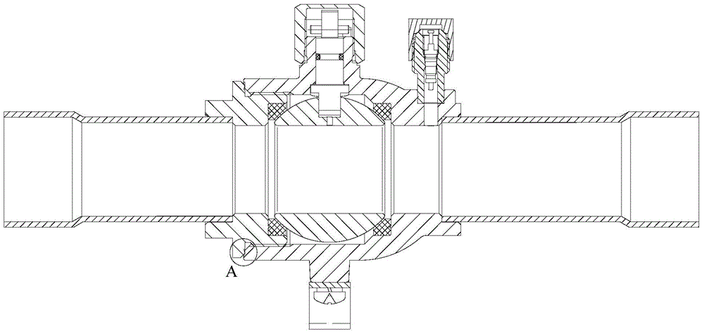
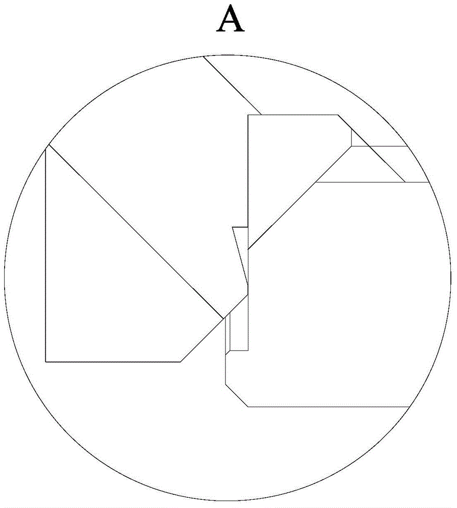
However, the sealing parts of the valve seat and the valve body of this structure require high precision, and the sealing parts are easy to be improperly protected during the production process, and the right-angled edges of the sealing part will be damaged, resulting in sealing failure and refrigerant in the valve body. Leakage; moreover, anaerobic glue is easy to deteriorate when heated, and loses its adhesive effect, which will cause the thread to loosen and cause the refrigerant in the valve body to leak. , The threaded connection between the valve seat and the valve body of the ball valve is unreliable, and the pipelines on both sides of the ball valve are usually subject to greater stress, which makes the ball valve vibrate with the pipeline in the whole machine. When the air conditioner is cooling or heating, the ball valve will be damaged. Shocked by heat and cold, threaded connections will loosen over time
When the thread of the ball valve is loose, the refrigerant will leak, which will reduce the refrigerant in the air conditioning system and affect the cooling effect

Method used


Image

  • Ball valve and air conditioner
  • Ball valve and air conditioner
  • Ball valve and air conditioner

Examples


Embodiment Construction

[0034] In order to be able to understand the above objectives, features and advantages of the present invention more clearly, the present invention will be further described in detail below in conjunction with the accompanying drawings and specific embodiments. It should be noted that the embodiments of the application and the features in the embodiments can be combined with each other if there is no conflict.

[0035] In the following description, many specific details are set forth in order to fully understand the present invention. However, the present invention can also be implemented in other ways different from those described here. Therefore, the scope of protection of the present invention is not subject to the specific implementations disclosed below. Limitations of cases.

[0036] Such as Figure 4 with Figure 5 As shown, an embodiment according to the first aspect of the present invention provides a ball valve for an air conditioner. The ball valve includes a valve body...


PUM


Abstract

The invention provides a ball valve and an air conditioner. The air conditioner comprises the ball valve; the ball valve comprises a valve body and a valve seat; the valve body comprises an assembly end, and a valve spool component is arranged in the valve body; the valve seat comprises a sealed end, and the sealed end of the valve seat and the assembly end of the valve body are hermetically connected by welding; a counter bore is arranged in the sealed end of the valve seat, a sealing ring is arranged in the counter bore, and an annular protrusion is arranged on the inner edge of the bottom surface of the counter bore and is used for keeping the sealing ring and the bottom surface of the counter bore separated. By the arrangement, self-airtightness and airtightness in opening and closing of the ball valve can be guaranteed, refrigerant leakage or inadequate closing of a refrigerant pipe never occur, and quality of the air conditioner is improved.

Description

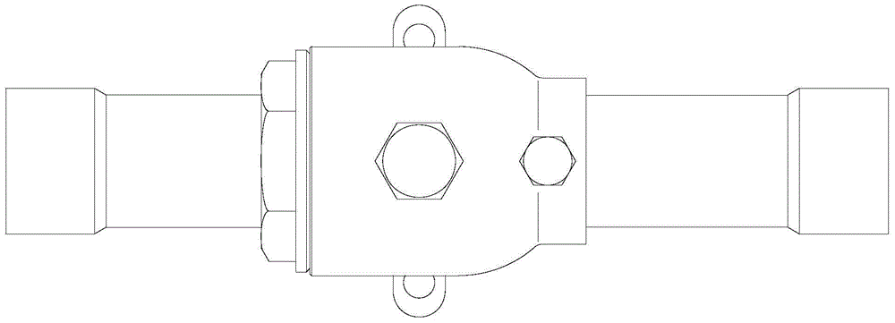
Technical field [0001] The present invention relates to the field of refrigeration, and more specifically, to a ball valve and an air conditioner having the ball valve. Background technique [0002] At present, some high-power multi-line air conditioners will use ball valves. The valve body of the ball valve is connected to the valve seat after the ball core and valve stem are installed. After that, the valve body and the valve seat need to be sealed, that is, the thread is added to the thread. Oxygen glue. Such as Figure 1 to Figure 3 As shown, the valve body and the valve seat of the conventional ball valve are threadedly connected. The threaded connection provides the valve body and the valve seat with anti-pressure required for sealing, and the anaerobic glue sticks to the thread to prevent the thread from loosening. However, the valve seat and the sealing part of the valve body of the ball valve of this structure require high precision, and the sealing part is easy to be im...

Claims


Application Information

Patent Timeline
Patent Type & Authority Applications(China)
IPC IPC(8): F16K5/06F16K5/08F16K27/06
CPCF16K5/0605F16K5/0689F16K5/0694F16K27/067
Inventor 尹举凌朱波郑健斌
Owner GD MIDEA HEATING & VENTILATING EQUIP CO LTD
Learn More