
Integrated structure of concrete tower drum and foundation of fan

A technology of concrete and reinforced concrete, which is applied in infrastructure engineering, wind turbines, wind turbine components, etc., and can solve problems such as waste, large volume of foundation ring, and high cost of foundation ring

Active Publication Date: 2015-05-13
健安诚(内蒙古)新能源科技有限公司
View PDF8 Cites 4 Cited by
  • Summary
  • Abstract
  • Description
  • Claims
  • Application Information

AI Technical Summary

Problems solved by technology

[0003] In the construction technology of the traditional concrete foundation, the foundation ring needs to be embedded in the foundation, and the foundation ring and the fan tower are connected by bolts. However, the installation and leveling of the foundation ring are complicated, the construction is difficult, and the cost of the foundation ring itself is high (about 140,000-180,000), the base ring is bulky and inconvenient to transport
[0004] The construction technology of the traditional concrete anchor-bolt link foundation needs to overlap the fan foundation and the fan tower respectively, and then drop the fan tower on the fan foundation, and the fan tower before the fan foundation needs to wait for the wind turbine foundation. When the strength of high-strength grouting material rises to the design strength, the cost of equipment and labor will be wasted during this period, resulting in long construction period and high cost

Method used


Image

  • Integrated structure of concrete tower drum and foundation of fan
  • Integrated structure of concrete tower drum and foundation of fan
  • Integrated structure of concrete tower drum and foundation of fan

Examples


Embodiment 1

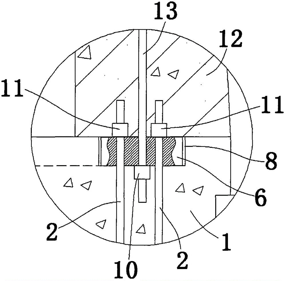
[0032] Such as figure 1 , 2 As shown, the reinforced concrete column 1 is embedded with first high-strength bolts that are evenly distributed on two concentric circles and are parallel to each other, forming a large circle and a small circle. The lower ends of the first high-strength bolts pass through the buried The bottom flange 3 at the bottom of the reinforced concrete column 1 is screwed to the first nut 5, and the bottom flange 3 is horizontally arranged in the reinforced concrete column 1, such as Figure 5A As shown, the bottom flange 3 is provided with first through holes 4 matched with the first high-strength bolts, and the first through holes 4 are evenly distributed on the bottom flange 3 in two concentric circles. The distribution of the first through holes 4 corresponds to the distribution of the first high-strength bolts; the upper ends of the first high-strength bolts extend vertically upwards, and the first high-strength bolts pass through the reinforced conc...

Embodiment 2

[0038] Except the following structures, other uniform structures are the same as Example 1:

[0039]Such as Figure 3B As shown, the top of the reinforced concrete column 1 corresponding to the position of the intermediate flange 6 is provided with a first groove 8 for embedding the intermediate flange 6, and the depth of the first groove 8 is smaller than that of the The thickness of the middle flange 6, the bottom of the reinforced concrete tower 12 corresponding to the position of the middle flange 6 is provided with a second groove 9 for embedding the middle flange 6, the second groove 9 The depth is smaller than the thickness of the middle flange 6 .

Embodiment 3

[0041] Such as Figure 8 As shown, the reinforced concrete column 1 is embedded with first high-strength bolts uniformly distributed on a concentric circle and parallel to each other, and the lower ends of the first high-strength bolts pass through the bottom embedded in the bottom of the reinforced concrete column 1 Flange 3 and threaded first nut 5, such as Figure 5B As shown, the first through holes 4 are provided on the bottom flange 3, and the first through holes 4 are evenly distributed in a circle.

[0042] The reinforced concrete tower 12 is embedded with second high-strength bolts 13 evenly distributed in a circle, and the circle surrounded by the second high-strength bolts 13 is concentric with the circle surrounded by the first high-strength bolts. The radius of the circle surrounded by the second high-strength bolts 13 is smaller than the radius of the circle surrounded by the first high-strength bolts.

[0043] Such as Figure 6B As shown, the intermediate fla...


PUM


Abstract

The invention relates to an integrated structure of a concrete tower drum and a foundation of a fan. The integrated structure comprises a reinforced concrete column body, wherein the reinforced concrete tower drum is arranged at the top of the reinforced concrete column body; first high-strength bolts distributed along the circumference are buried in the reinforced concrete column body; bottom flanges are fixed at the lower ends of the first high-strength bolts; middle flanges are fixedly connected to the upper ends of the first high-strength bolts; second high-strength bolts distributed along the circumference are buried in the reinforced concrete tower drum; the lower ends of the second high-strength bolts are fixedly connected with the middle flanges; the upper ends of the second high-strength bolts are fixedly connected with top flanges. Compared with a conventional combination of a steel fan tower drum and a fan foundation, the integrated structure disclosed by the invention has the advantages that the manufacturing cost is reduced; furthermore, a foundation ring for connecting the fan foundation with the tower drum in the conventional technology is eliminated, so that the manufacturing cost is reduced; the concrete tower drum selects on-site pouring or factory production and transportation according to conditions of a construction site and a transportation road, so that transportation is facilitated. Compared with a conventional fan, the integrated structure disclosed by the invention further has the advantages that hoisting of the tower drum is avoided, and the working period is shortened.

Description

technical field [0001] The invention relates to the field of large wind turbines, in particular to an integrated structure of a wind turbine concrete tower and foundation. Background technique [0002] At present, for the fixing of large or super large equipment racks and towers, including wind generators, wind turbines, power line street lighting and signaling devices, bridge supports, commercial signs, highway signs, ski lifts, etc. Constructed concrete support foundation. [0003] In the construction technology of the traditional concrete foundation, the foundation ring needs to be embedded in the foundation, and the foundation ring and the fan tower are connected by bolts. However, the installation and leveling of the foundation ring are complicated, the construction is difficult, and the cost of the foundation ring itself is high (about 140,000-180,000), the base ring is bulky and inconvenient to transport. [0004] The construction technology of the traditional concr...

Claims


Application Information

Patent Timeline
IPC IPC(8): E04H12/12E02D27/42F03D11/04
CPCY02E10/72Y02E10/728Y02P70/50
Inventor 马利鑫陈宝民
Owner 健安诚(内蒙古)新能源科技有限公司
Learn More