Low-strength fiber stretch-breaking and slivering device
A technology of strong fiber, pulling and cutting and making sliver, applied in the direction of fiber bundles into fiber sliver/yarn, etc., can solve the problems of difficult carding of low-strength functional fibers, etc., to reduce the pulling force and reduce the pulling force Effect
- Summary
- Abstract
- Description
- Claims
- Application Information
AI Technical Summary
Problems solved by technology
Method used
Image
Examples
Embodiment 1
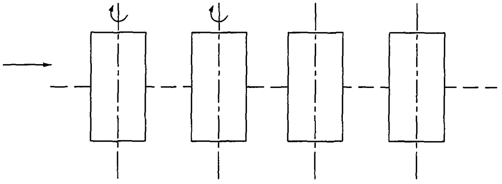
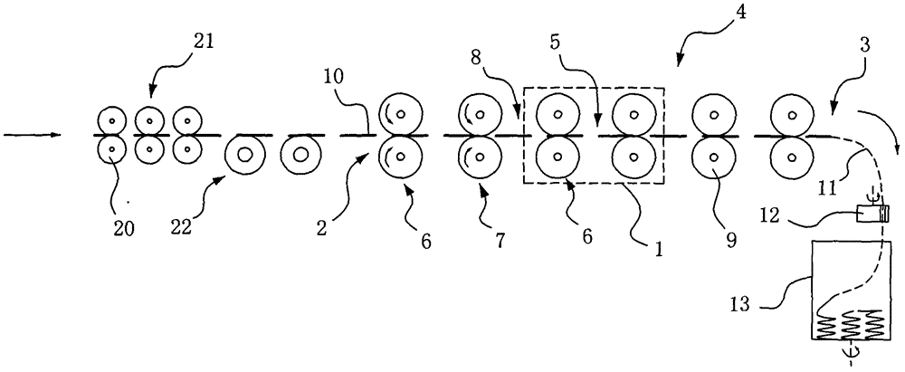
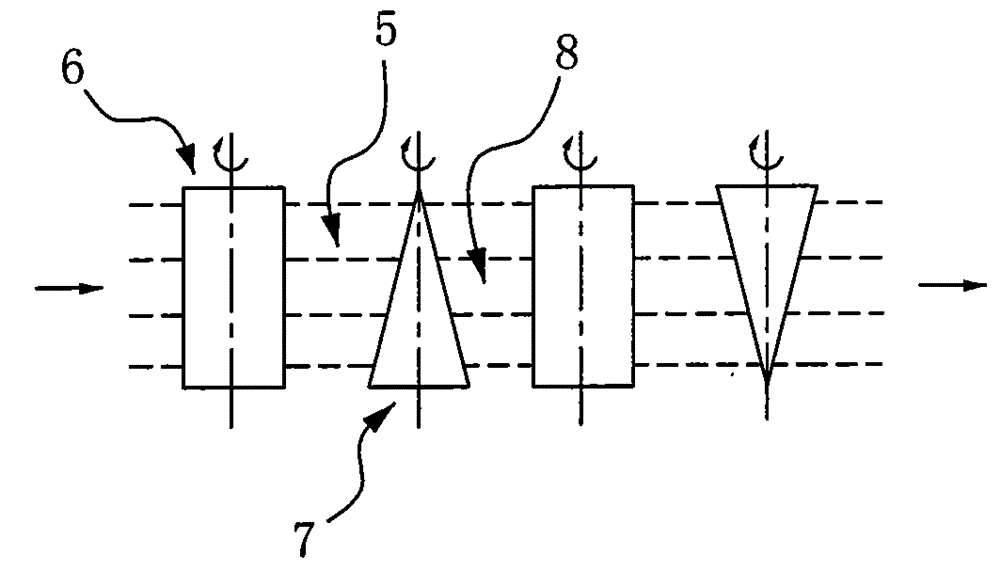
[0036] Such as figure 1 Shown is a schematic diagram of the structure of a traditional pull-cutting roller set, such as figure 2 , 3 As shown, a low-strength fiber drafting and cutting device includes a drafting device 4 with a feeding end 2 and a discharging end 3 composed of multiple sets of drafting rollers 1, each of which A drafting zone 5 is formed between 1 and each set of drafting rollers 1 is composed of a pair of meshing drafting rollers 6 and a pair of drafting rollers 7 respectively. The drafting transition zone 8 is formed between the cutting roller 7 and the drafting roller 6. The drafting roller 6 and the drafting roller 7 are composed of two roller bodies 9 that mesh with each other. The drafting in each drafting zone 5 The horizontal distance between the roller 6 and the pulling roller 7 along the axis of the roller body 9 gradually increases or gradually decreases. In this embodiment, in order to realize that the horizontal distance between the draft roller 6...
Embodiment 2
[0043] The same parts of this embodiment and Embodiment 1 will not be repeated here, and the difference lies in: Figure 4 As shown, the longitudinal cross-sectional shape of the roller body 15 of the pulling roller 14 in the axial direction is set to a trapezoidal structure. The roller bodies 15 of the adjacent pulling rollers 14 are parallel to each other and are installed oppositely.
Embodiment 3
[0045] The same parts of this embodiment and Embodiment 1 will not be repeated here, and the difference lies in: Figure 5 As shown, the horizontal distance between the draft roller 17 and the draft roller 18 in each of the draft cutting zones 16 along the axis of the roller body 19 changes alternately. The longitudinal cross-sectional shape of the roller body 19 of the pulling roller 18 in the axial direction is configured as a wave structure.
PUM
| Property | Measurement | Unit |
|---|---|---|
| length | aaaaa | aaaaa |
Abstract
Description
Claims
Application Information
 - R&D Engineer
- R&D Manager
- IP Professional
- Industry Leading Data Capabilities
- Powerful AI technology
- Patent DNA Extraction
Browse by: Latest US Patents, China's latest patents, Technical Efficacy Thesaurus, Application Domain, Technology Topic, Popular Technical Reports.
© 2024 PatSnap. All rights reserved.Legal|Privacy policy|Modern Slavery Act Transparency Statement|Sitemap|About US| Contact US: help@patsnap.com


