
Rotating type rigidity-changing flexible joint

A technology of flexible joints and variable stiffness, which is applied in the field of robotics, can solve the problems of not being able to adapt to fast motion and impact, the joint flexible deformation angle is limited, and the unfavorable application of joint robots, etc., to reduce the spring volume, realize flexible output, reduce The effect of small power requirements

Active Publication Date: 2015-05-13
HEBEI UNIV OF TECH
View PDF9 Cites 56 Cited by
  • Summary
  • Abstract
  • Description
  • Claims
  • Application Information

AI Technical Summary

Problems solved by technology

[0005] Most of the existing flexible joints based on serial actuators still focus on the realization of flexible output, and the structure is complex, and the angle of flexible deformation of the joint is limited. For example, a cylindrical series elastic actuator disclosed in Patent No. CN102211622A has a complex structure and It can only produce linear motion, and the stiffness is not adjustable, which is not conducive to the application on joint robots; another example is the humanoid robot disclosed in the CN101934525B patent with variable stiffness and flexible joint design. Although the purpose of actively variable stiffness output is achieved, the structure is also complicated , and the drive relies on flexible cables, which cannot adapt to rapid movement and impact, and the extensiveness of application to various articulated robots is limited

Method used


Image

  • Rotating type rigidity-changing flexible joint
  • Rotating type rigidity-changing flexible joint
  • Rotating type rigidity-changing flexible joint

Examples


Embodiment Construction

[0027] Further describe the present invention below in conjunction with embodiment and accompanying drawing thereof. However, the protection scope of the claims of the present application is not limited to the description scope of the embodiments.

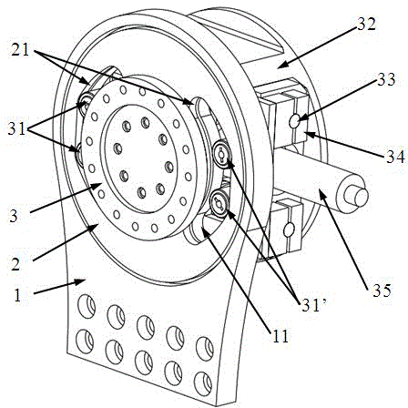
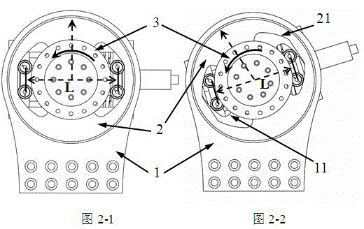
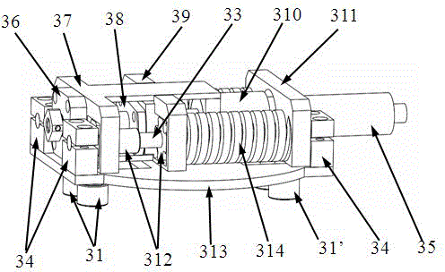
[0028] A kind of rotary variable stiffness flexible joint designed by the present invention (flexible joint for short, see Figure 1-5 ), including a passive variable stiffness mechanism and an active flexible drive mechanism, characterized in that the passive variable stiffness mechanism mainly includes: joint output disc 1, joint first drive disc 2, joint second drive disc 3, first cam group 31, The second cam group 31', the first cam group mounting seat 37, the second cam group mounting seat 311, the optical shaft 33, the optical shaft support seat 34, the stiffness adjustment mounting plate 313, the linear bearing 312 and the compression spring 314, the joint The first drive disc 2 is fixedly connected to the second drive disc...


PUM


Abstract

The invention discloses a rotating type rigidity-changing flexible joint which comprises a driven rigidity-changing mechanism and a driving flexible drive mechanism. The rotating type rigidity-changing flexible joint is characterized in that the driven rigidity-changing mechanism mainly comprises an output plate of the joint, a first drive plate of the joint, a second drive plate of the joint, a first cam set, a second cam set, a first cam set installing base, a second cam set installing base, a bare shaft, a supporting base of the bare shaft, a rigidity adjusting installing plate, a linear bearing and a spring. The first drive plate of the joint is fixedly connected with the second drive plate of the joint. The second drive plate of the joint and the output plate of the joint are provided with cam grooves with the same outline. By means of the outlines, the equivalent rigidity of the joint can change along with the flexible deformation angle of the joint. Cams of the first cam set and the second cam set can make contact with the second drive plate and the output plate of the joint at the same time. The driving flexible drive mechanism mainly comprises a trapezoidal lead screw, a lead screw supporting base, a lead screw nut, a lead screw bearing, a direct-current servo motor, a motor installing base, a coupler, a rigidity-changing adjusting base, a linear bearing and a spring.

Description

technical field [0001] The invention relates to robot technology, in particular to a rotary variable stiffness flexible joint. Background technique [0002] The articulated robot is designed according to the principle of bionics. It has a simple structure and flexible activities. It shows strong adaptability to work in various complex environments. It has been widely used in industrial production, scientific research and exploration, earthquake relief and other fields. The rotary joint is the most important part of the robot, which is of great significance to the normal work, stability, reliability and precision of the robot. The joints of traditional rigid robots can run smoothly in a known environment, but in unknown environments or accidents, they are very vulnerable to shocks and cause damage to people or themselves, especially as robots are getting closer to human life. To popularize in daily life, the priority needs to be solved are the problems of poor safety and poo...

Claims


Application Information

Patent Timeline
Patent Type & Authority Applications(China)
IPC IPC(8): B25J17/00
Inventor 张小俊史延雷张冬孙凌宇张明路
Owner HEBEI UNIV OF TECH
Learn More