A suture cutting assembly steering mechanism for surgical staplers

A technique of surgical suturing and steering mechanism, applied in the direction of surgical fixation nails, etc., can solve the problems of long unfavorable recovery time for patients, large incisions for surgical patients, inconvenient operation by doctors, etc., and achieves the effects of compact structure, easy hand feeling, firm and reliable locking

Active Publication Date: 2016-08-24
JIANGSU ZIHANG PRECISION HARDWARE
View PDF5 Cites 0 Cited by
  • Summary
  • Abstract
  • Description
  • Claims
  • Application Information

AI Technical Summary

Problems solved by technology

[0003] At present, the cutting and stapling devices are all open-type cutting and stapling devices. The volume of the instruments is relatively large, and the incision of the surgical patient is relatively large, which is unfavorable for the patient's recovery time and increases the pain of the patient.
The current endocavity cutting and stapler doctors need to use both hands to forcibly rotate the steering handle to adjust the angle during the operation, which brings inconvenience to the doctor's operation

Method used


Image

  • A suture cutting assembly steering mechanism for surgical staplers
  • A suture cutting assembly steering mechanism for surgical staplers
  • A suture cutting assembly steering mechanism for surgical staplers

Examples


Embodiment Construction

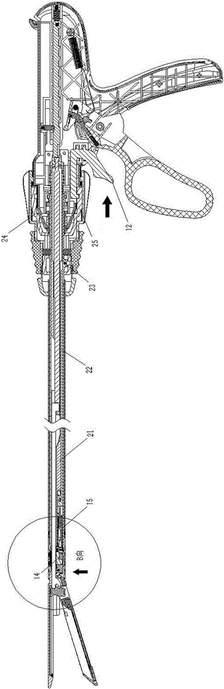
[0044] Refer to attached Figure 1-18 , a sewing and cutting assembly steering mechanism for a surgical stapler includes a corner handle 12, an upper angle driving ring 24, a lower angle driving ring 25, a steering hook 22, a steering positioning card 15, a steering positioning card compression spring 16, and a support seat 17 , Steering support bar 18, steering support bar clip spring 19, steering head 14, blade holder 20 and positioning guide support tube 21.

[0045]The corner handle 12 can be configured as a slide button or a button structure. The corner handle 12 is installed in the corner handle installation sliding groove 10-1 at the front bottom of the fixed handle 10 through the corner handle positioning boss 12-2. Upper angle driving ring 24 and lower angle driving ring 25 are set on the front end of fixed handle 10, and the corner handle cam 12-1 at the front end of corner handle 12 is installed on the corner handle cam mounting groove 25 of the upper angle driving...


PUM


Abstract

The invention relates to a sewing and cutting subassembly steering mechanism for a surgical stitching instrument. The sewing and cutting subassembly steering mechanism is an assorted device of the surgical stitching instrument, is used for applying linear rows to an intracavitary tissue and cutting off the tissue between the linear rows, and is used for a sewing and cutting subassembly consisting of a nail abutting seat and a cutting knife nail bin. The sewing and cutting subassembly steering mechanism for the surgical stitching instrument comprises a corner handle, an upper angular driving ring, a lower angular driving ring, a steering drag hook, a steering and positioning clamp, a steering and positioning clamp pressure spring, a supporting seat, a steering and supporting strip, a steering and supporting strip pressure spring, a steering head, a blade support and a positioning, guiding and supporting tube, wherein the corner handle is arranged in a corner handle mounting sliding groove in the front lower portion of a fixing handle through a corner handle positioning projection; the upper angular driving ring and the lower angular driving ring sleeve the front end of the fixing handle; the steering drag hook is connected with a pin hole in the front end of the lower angular driving ring through the steering drag hook pin; and the front end of the blade support is connected with a blade support cam positioning semi-recessed round groove in the steering head through a blade support cam.

Description

technical field [0001] The invention relates to a steering mechanism of a suturing and cutting assembly for a surgical stapler, which is a surgical stapler matching device that applies a linear row to the tissue in a cavity and cuts tissue between the linear row of staplers at the same time. It is the steering mechanism of the sewing and cutting assembly composed of the cutting knife and the staple magazine of the anvil. Background technique [0002] During laparoscopic and or endoscopic surgery, the procedure is performed through a small incision in the patient or through a narrow cannula inserted into the wound. In traditional or open procedures, the doctor has direct access to the surgical site. The abdominal operating table offers advantages over open surgery due to its reduced patient trauma, shortened patient recovery period, and significantly lower overall costs. To meet the specific needs of endoscopic and intraperitoneal, endoscopic suturing devices have been deve...

Claims


Application Information

Patent Timeline
Patent Type & Authority Patents(China)
IPC IPC(8): A61B17/072
CPCA61B17/0682A61B17/07207A61B2017/07285
Inventor 王超航
Owner JIANGSU ZIHANG PRECISION HARDWARE
Why Eureka
Try Eureka