
Method for determining the position of an electric motor in a clutch actuation system of a motor vehicle

A clutch control and motor technology, applied in the direction of clutch, motor control, electronic commutation motor control, etc., can solve the problems of no correlation between increment and motor, motor can not be positioned arbitrarily, sensor signal resolution is limited, etc.

Inactive Publication Date: 2018-01-16
SCHAEFFLER TECH AG & CO KG
View PDF5 Cites 0 Cited by
  • Summary
  • Abstract
  • Description
  • Claims
  • Application Information

AI Technical Summary

Problems solved by technology

[0004] The disadvantage of Hall switches is therefore that the motor cannot be positioned arbitrarily and the resolution of the sensor signal is only limited
High-resolution incremental sensors have the disadvantage that there is no dependence of the increment on the commutation time of the motor after switching on the supply voltage

Method used


Image

  • Method for determining the position of an electric motor in a clutch actuation system of a motor vehicle
  • Method for determining the position of an electric motor in a clutch actuation system of a motor vehicle
  • Method for determining the position of an electric motor in a clutch actuation system of a motor vehicle

Examples


Embodiment Construction

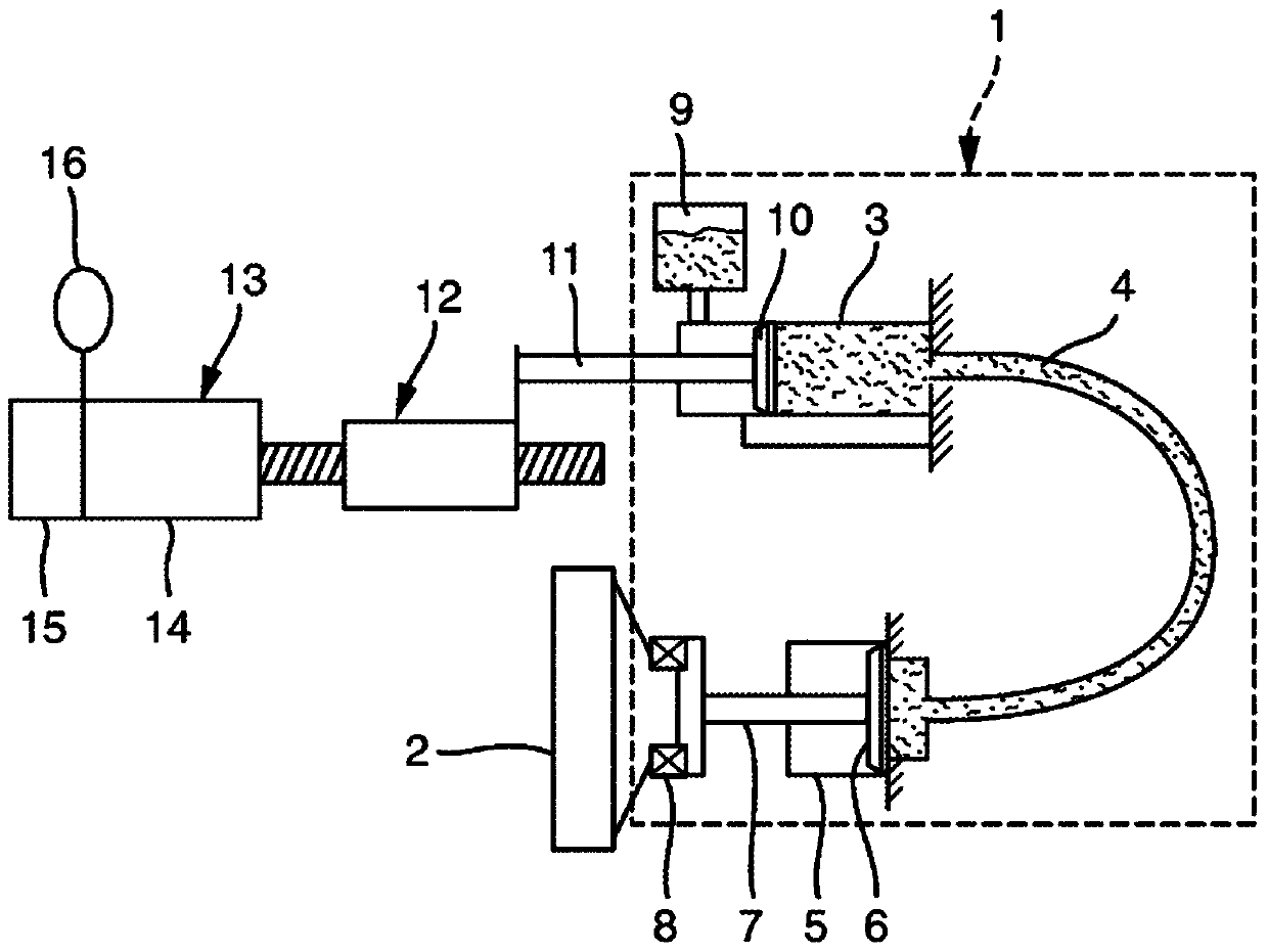
[0022] exist figure 1 A clutch actuation system 1 for an automated clutch is shown in simplified form in . A clutch actuation system 1 is associated with a friction clutch 2 in the drive train of a motor vehicle and comprises a master cylinder 3 which is connected to a slave cylinder 5 via a hydraulic line 4 , also referred to as a pressure line. In the slave cylinder 5 , a slave piston 6 is movable to and fro, which actuates the friction clutch 2 via the actuating mechanism 7 and with the insertion of the bearing 8 .

[0023] The master cylinder 3 can be connected to a compensating container 9 via a connection opening. The master piston 10 is movable in the master cylinder 3 . Starting from the main piston 10 , a piston rod 11 is movable in translation along the longitudinal extension of the master cylinder 3 together with the main piston 10 . The piston rod 11 of the master cylinder 3 is coupled via a spindle 12 to an electric actuating drive 13 . Electric actuating driv...


PUM


Abstract

The invention relates to a method for determining the position of an electric motor, in particular in a clutch actuating system of a motor vehicle, wherein a position signal of a rotor of the electric motor is provided by an electric motor stator outside the axis of rotation of the electric motor The sensor is received, and the position signal is evaluated by an evaluation unit with respect to the position of the electric motor. In order to avoid position adjustment of the motor at the belt ends, the rotor is charged with voltage in its standstill state and a response corresponding to the position of the rotor is associated with the commutation of the motor.

Description

technical field [0001] The invention relates to a method for determining the position of an electric motor, in particular in a clutch actuating system of a motor vehicle, wherein a position signal of the rotor of the electric motor is received by a sensor arranged on the stator of the electric motor outside the axis of rotation of the electric motor, so The position signal is evaluated by an evaluation unit with respect to the position of the electric motor. Background technique [0002] In modern motor vehicles, especially passenger cars, automated clutches are increasingly being used, as described in DE 10 2011 014 936 A1. The use of such a clutch has the advantage of improving driving comfort and results in the possibility of more frequent driving in gears with large transmission ratios. The clutches used here are used in hydraulic clutch systems in which an electrohydraulic actuator driven by an electrically commutated electric motor is connected to the clutch via hydra...

Claims


Application Information

Patent Timeline
Patent Type & Authority Patents(China)
IPC IPC(8): H02P6/18F16D48/06
CPCH02P6/185F16D48/064F16D48/066F16D2500/1024F16D2500/1025F16D2500/3026F16D2500/5012F16D2500/7041F16D2500/7042H02P2203/03
Inventor 马库斯·迪特里希
Owner SCHAEFFLER TECH AG & CO KG
Learn More