
System and method for wireless network signal scope sensing and displaying

A technology of wireless network signal and range, applied in the field of signal detection system, can solve the problem of limited number of positions reported by in-vehicle equipment, transmission range will not be similar, etc.

Inactive Publication Date: 2015-05-06
CHUNGHWA TELECOM CO LTD
View PDF5 Cites 6 Cited by
  • Summary
  • Abstract
  • Description
  • Claims
  • Application Information

AI Technical Summary

Problems solved by technology

However, in real life, the network signal may be affected by the environment and shelter, resulting in the transmission range may not be like the ideal circle or sector
In addition, there are also related existing technologies that use vehicle-mounted equipment to drive on the road and collect the cell identification codes and signal strengths corresponding to each location point. However, if the road sections that have not been driven will not be able to know their signal conditions, this method may be affected. Limited to the number of locations reported by the vehicle

Method used


Image

  • System and method for wireless network signal scope sensing and displaying
  • System and method for wireless network signal scope sensing and displaying
  • System and method for wireless network signal scope sensing and displaying

Examples


Embodiment Construction

[0039] In order to make the purpose, technical solution and advantages of the present invention clearer, the present invention will be further described in detail below in conjunction with the accompanying drawings.

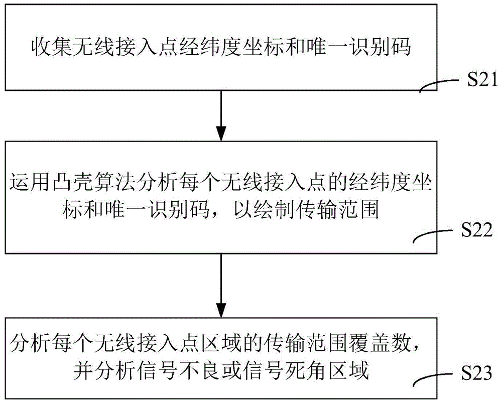
[0040] see figure 1 , is a schematic diagram of the system architecture of wireless network signal range detection and display in the present invention, the system includes wireless access point 101, wireless access point 102, wireless access point 103, vehicle terminal equipment 201, vehicle terminal equipment 202, vehicle The terminal device 203 , the vehicle terminal device 204 , the vehicle terminal device 205 , the cloud computing server 300 and the cloud history database 400 . When the vehicle-mounted terminal device 201 connects to the wireless access point 101 at the time point t1, record the latitude and longitude coordinates at the time point t1 and the unique identification code of the wireless access point 101, and keep moving, and detect at the same ...


PUM


Abstract

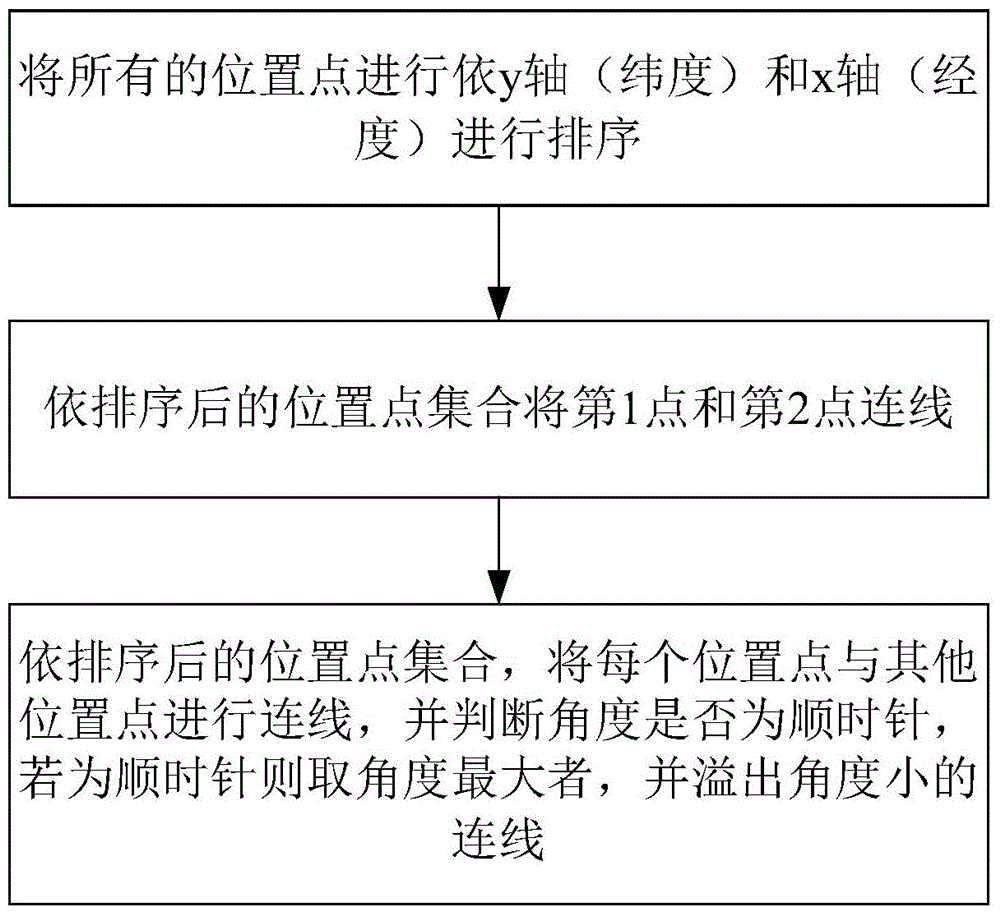
The invention provides a system and a method for wireless network signal scope sensing and displaying. A vehicle-mounted terminal device periodically obtains present wireless network signals and a latitude and longitude coordinate, and periodically sends the wireless network signals and the latitude and longitude coordinate back to a rear-end cloud server. The cloud server can draw a transmission scope of each region according to the wireless network signals and the latitude and longitude coordinate set back by the vehicle-mounted device and by means of a convex hull algorithm. Thus signal conditions in road segments which no vehicle passes can be compensated. Conditions that a same area is covered by a plurality of regions are analyzed according to the transmission scope. Which area is not covered by any region or is only covered by one region and located at the edge of the region is determined according to the region covering conditions, thus determination of poor mobile communication receiving or communication corner areas is realized, and reference is provided for operating supporting.

Description

【Technical field】 [0001] The present invention is a signal detection system and method, especially a system and method for wireless network signal range detection and display. 【Background technique】 [0002] At present, in many existing technologies, the transmission range of the base station is assumed to be circular or fan-shaped, and a specific transmission distance is given. However, in real life, the network signal may be affected by the environment and shelters, resulting in a transmission range that may not be as ideal as a circle or fan. In addition, there are also related existing technologies that use vehicle-mounted equipment to drive on the road and collect the cell identification codes and signal strengths corresponding to each location point. However, if the road sections that have not been driven will not be able to know their signal conditions, this method may be affected. Limited to the number of locations reported by the on-board device. 【Content of inve...

Claims


Application Information

Patent Timeline
Patent Type & Authority Applications(China)
IPC IPC(8): H04W24/08
CPCH04W24/08
Inventor 陈志华林佳宏官大勝
Owner CHUNGHWA TELECOM CO LTD
Learn More