
Video monitoring system based on optical fiber transmission and working method thereof

A technology of video surveillance system and working method, which is applied in the direction of television system, closed-circuit television system, and parts of television system adapted to optical transmission, to achieve high reliability and real-time effects

Active Publication Date: 2015-05-06
HOHAI UNIV CHANGZHOU
View PDF5 Cites 0 Cited by
  • Summary
  • Abstract
  • Description
  • Claims
  • Application Information

AI Technical Summary

Problems solved by technology

[0008] The purpose of the present invention is to provide a video monitoring system based on optical fiber transmission and its working method, to solve the technical problem of filtering out video noise, and then maintain the smoothness of video display on the basis of ensuring the integrity and sharpness of video information

Method used


Image

  • Video monitoring system based on optical fiber transmission and working method thereof
  • Video monitoring system based on optical fiber transmission and working method thereof
  • Video monitoring system based on optical fiber transmission and working method thereof

Examples


Embodiment 1

[0041] In the prior art, since the video is produced by continuous playing of several frames of images, the present invention decomposes the video into several frames of images for corresponding processing.

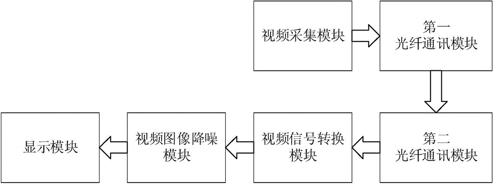
[0042] Such as figure 1 As shown, the video monitoring system based on optical fiber transmission of the present invention includes: a video acquisition module, a first optical fiber communication module connected to the video acquisition module, the first optical fiber communication module is connected to the second optical fiber communication module through an optical fiber, The second optical fiber communication module is connected to the video signal conversion module, and the video signal conversion module is connected to the display module through the video image noise reduction module.

[0043] The video signal conversion module is suitable for converting video signals transmitted by optical fibers into video images.

[0044] The video image noise reduction module...

Embodiment 2

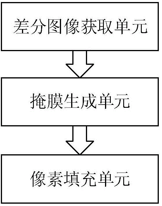
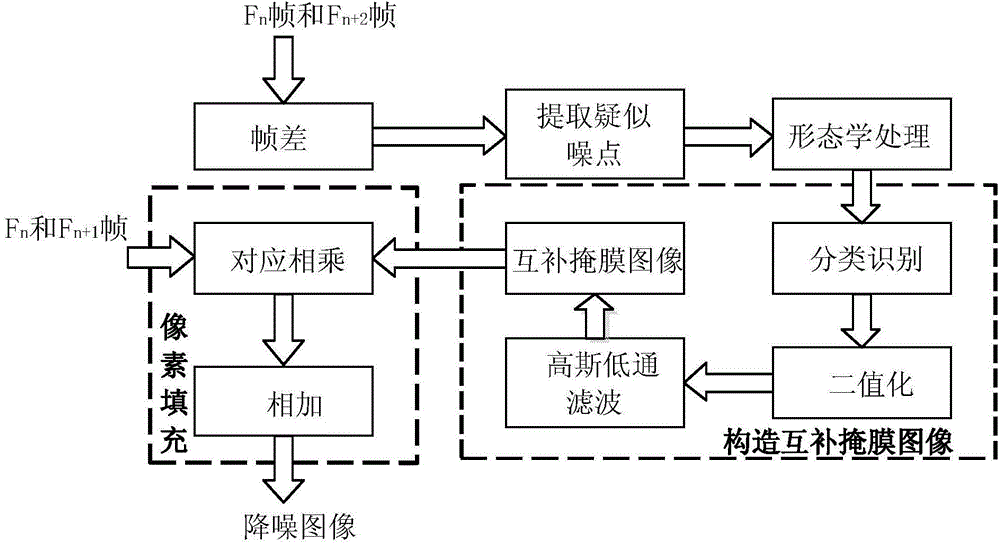
[0051] Such as Figure 3 to Figure 5 As shown, on the basis of Embodiment 1, the present invention also provides a working method of the video surveillance system, which includes: the video image noise reduction method of the video image noise reduction module, that is, to obtain the difference of the interval frame image image, extracting the noise region contained in the difference image, and generating a corresponding mask image; and filling the noise pixel position of the mask image with the pixels of the corresponding position of the intermediate frame image on the first frame image to obtain Noise-reduced image.

[0052] After the above-mentioned original video image undergoes continuous processing of image frames by the video image noise reduction method, it is restored to a denoised video image.

[0053] Further, the method for obtaining the differential image includes:

[0054] Using the frame difference method to obtain the absolute value of the difference between ...


PUM


Abstract

The invention disclosers a video monitoring system based on optical fiber transmission and a working method thereof. The video monitoring system comprises a video collection module, a first optical fiber communication module connected with the video collection module, the first optical fiber communication module is connected with a second optical fiber communication module through an optical fiber, the second optical fiber communication module is connected with a video signal conversion module, and the video signal conversion module is connected with a display module through a video image noise reduction module. By means of the system and the working method, almost all particle noise point targets of the video image in the video monitoring system can be effectively extracted, moving information in an original video is well maintained and not lost, and high reliability and real-time performance are achieved. No new noise can be introduced in an image after noise reduction, and the acutance of an original image is not reduced.

Description

technical field [0001] The patent of the present invention relates to the technical field of monitoring and processing based on optical fiber transmission of video signals, especially the technical field of noise reduction and enhancement of video sequences. Background technique [0002] Video surveillance has the advantages of intuition, convenience, reliability, and rich information content, so it is widely used in finance, commerce, transportation, residences, communities, etc., and plays an important role in environmental monitoring and safety precautions in these fields. The optical fiber transmission system has the advantages of long transmission distance, large information capacity, strong anti-interference ability, and good confidentiality, and has become an important means of communication. The use of optical fiber technology to transmit images can effectively ensure that image data will not be stolen, and it has the characteristics of high sensitivity and high reso...

Claims


Application Information

Patent Timeline
Patent Type & Authority Applications(China)
IPC IPC(8): H04N7/18H04N5/21H04N7/22
Inventor 许海燕牟丽张学武张卓
Owner HOHAI UNIV CHANGZHOU
Learn More