Eureka AIR delivers breakthrough ideas for toughest innovation challenges, trusted by R&D personnel around the world.

Fiber communication protocol used for distributed controller and realization device thereof

A technology of distributed controller and optical fiber communication, applied in the direction of instruments, electrical digital data processing, etc., can solve problems such as the difficulty of meeting the arbitration loop protocol, the communication delay between nodes cannot be determined, etc., to achieve high bus utilization and improve bus utilization. rate, transmission delay controllable effect

Active Publication Date: 2015-05-06
BEIJING RES INST OF PRECISE MECHATRONICS CONTROLS +1
View PDF3 Cites 4 Cited by
  • Summary
  • Abstract
  • Description
  • Claims
  • Application Information

AI Technical Summary

Problems solved by technology

[0004] In the Fiber Channel arbitrated ring protocol, the communication delay between nodes cannot be determined. Only when the nodes on the ring detect that the bus is idle can they obtain the right to use the bus through arbitration, thereby establishing a two-way connection with the destination node. The destination node directly lets the data pass through. At any time, only one pair of nodes uses the bus, and other nodes can only obtain arbitration until they give up the right to use the bus.
[0005] In the communication process between the flight control system and the servo system, the servo system adopts distributed control, and each node on the bus loop needs to respond to the command in the same command cycle and return the measurement information to the master node. The arbitration loop protocol cannot meet the above requirements, and it is necessary to design a A Fiber Optic Communication Protocol Applicable to Distributed Control System

Method used


Image

  • Fiber communication protocol used for distributed controller and realization device thereof
  • Fiber communication protocol used for distributed controller and realization device thereof
  • Fiber communication protocol used for distributed controller and realization device thereof

Examples


Embodiment Construction

[0043] The present invention will be described in further detail below in conjunction with the accompanying drawings and embodiments.

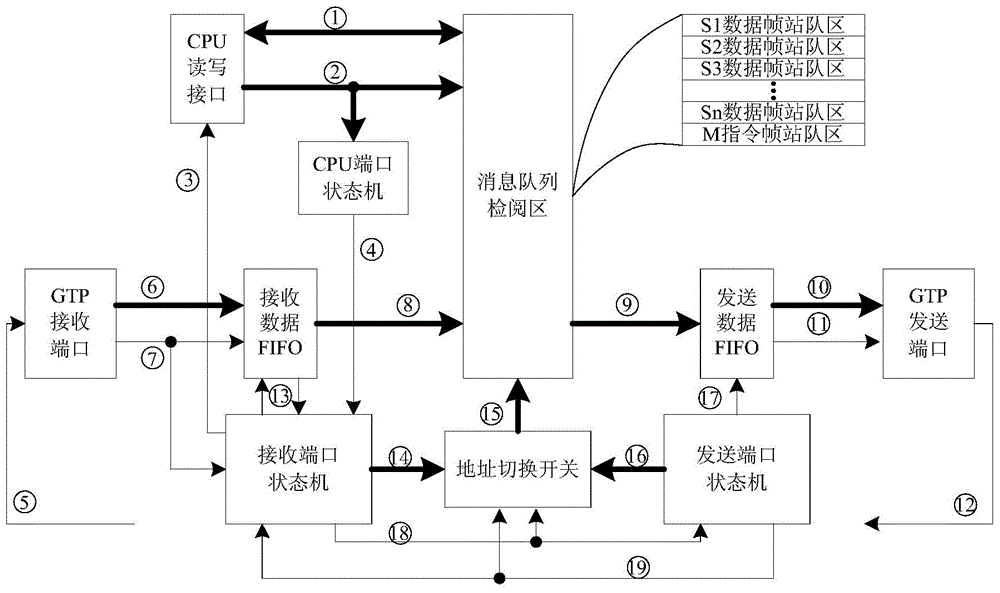
[0044] as attached figure 1 Shown is the carrier of the optical fiber communication protocol of the distributed controller, including the master controller node M (M node for short), and multiple slave controller nodes S 1 ~S n (referred to as S node), the communication medium can be optical fiber but not limited to optical fiber medium, and can also be a medium that can transmit differential signals such as coaxial cable or twisted-pair shielded wire.

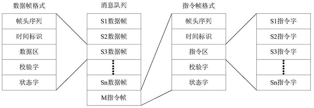
[0045] A ring topology protocol of "queue inspection ring" is proposed. The M node sends out instructions, and each S node receives the instruction and forwards the instruction to the next node; after each S node responds to the instruction, S 1 The node sends the data of this node to S 2 Node transmission, S 2 Node will S 1 Node data and S 2 Node data to S 3 Node transmission, thus, ea...


PUM


Abstract

The invention relates to a fiber communication protocol used for a distributed controller. An M node writes an instruction frame signal into an M instruction frame queue zone and sends the instruction frame signal to an S1 node; the S1 node stores an instruction frame into the M instruction frame queue zone and forwards the instruction frame to a next S node, and by parity of reasoning, an Sn node sends the instruction frame to the M node and covers the M instruction frame queue zone; for the S1 node, a data frame is directly transmitted to a next node; for the Sn (n is greater than or equal to 2) node, the data frame of a previous node and the data frame of a current node are received to form a new message queue, and the new message queue is transmitted to the next node; by parity of reasoning, the message queue of the Sn node comprises the data frames of all S nodes and is transmitted to the M node; and after the M node detects a data frame signal, the data frame is written into each node data frame queue zone of the message queue, and the data frame and the previous received and covered instruction frame form a complete message queue. In one instruction period, data interaction between a master controller node and each slave controller node is realized.

Description

technical field [0001] The invention relates to an optical fiber communication protocol for distributed controllers, in particular to an optical fiber communication protocol used as an actuator in a flight control system. The invention also relates to a device for realizing the optical fiber communication protocol. Background technique [0002] In the arrow-borne flight control system, the MTL-STD-1553B bus is mainly used for communication between the control system and the servo system, measurement system, and platform equipment. As the first generation of military communication bus technology, the MTL-STD-1553B bus adopts the command response mode , the control system issues an instruction, and the target subsystem returns a message to the control system after responding to the instruction. The MTL-STD-1553B bus rate is up to 1Mbps, with up to 32 nodes on the bus, and 1553B shielded cables are used as the transmission medium; as aerospace products have higher and higher r...

Claims


Application Information

Patent Timeline
Patent Type & Authority Applications(China)
IPC IPC(8): G06F13/38G06F13/42
CPCG06F13/382G06F13/4265
Inventor 王首浩王怀侠仲悦何宇昂
Owner BEIJING RES INST OF PRECISE MECHATRONICS CONTROLS
Why Eureka
Eureka Blog
Learn More