
Camera lens

A technology of camera lens and lens, applied in the field of camera lens

Active Publication Date: 2015-05-06
ZHEJIANG SUNNY OPTICAL CO LTD
View PDF6 Cites 51 Cited by
  • Summary
  • Abstract
  • Description
  • Claims
  • Application Information

AI Technical Summary

Problems solved by technology

[0003] At present, most of the camera lenses used in portable electronic products are three- to five-chip camera lenses, but with the popularity of portable electronic products, the miniaturized cameras have higher and higher requirements for pixels and image quality. Camera lenses will not be able to meet the needs of electronic products, so a camera lens for portable electronic products is needed, which can meet the miniaturization characteristics of electronic products on the basis of high pixels and high-quality images

Method used


Image

  • Camera lens
  • Camera lens
  • Camera lens

Examples


Embodiment 1

[0166] In Embodiment 1, the camera lens satisfies the conditions of the following table:

[0167] Table 1

[0168]

[0169]

[0170] Table 2

[0171] surface number

A4

A6

A8

A10

A12

S1

-6.1281E-03

4.3661E-03

0.0000E+00

0.0000E+00

0.0000E+00

S2

-1.0340E-02

-2.8693E-03

0.0000E+00

0.0000E+00

0.0000E+00

S3

-1.0662E-01

1.5664E-02

0.0000E+00

0.0000E+00

0.0000E+00

S4

-8.0168E-02

4.9781E-02

0.0000E+00

0.0000E+00

0.0000E+00

S5

-1.2354E-02

1.9507E-02

0.0000E+00

0.0000E+00

0.0000E+00

S6

-1.5146E-02

2.2755E-02

0.0000E+00

0.0000E+00

0.0000E+00

S7

-4.8131E-02

4.9967E-02

0.0000E+00

0.0000E+00

0.0000E+00

S8

-5.6105E-02

1.5113E-02

0.0000E+00

0.0000E+00

0.0000E+00

S9

3.5339E-02

-2.9113E-02

0.0000E+00

0.0000E+00

0.0000E+00 ...

Embodiment 2

[0175] In Embodiment 2, the camera lens satisfies the conditions of the following table:

[0176] table 3

[0177]

[0178] Table 4

[0179]

[0180]

[0181] In addition, TTL=6.06mm; f1=5.25mm; f2=-7.49mm; f3=8.35mm; f4=19.3mm; f5=6.63mm; f6=36.3mm; f7=-3.23mm and f=5mm; Semi- FOV=29.1°; aperture value: 2.2.

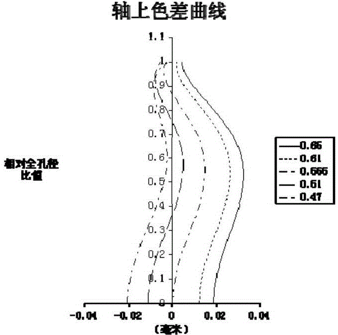
[0182] Figure 7 is the axial chromatic aberration diagram (mm) of the imaging lens of embodiment 2, Figure 8 is the astigmatism diagram (mm) of the imaging lens of embodiment 2, Figure 9 is the distortion figure (%) of the imaging lens of embodiment 2, Figure 10 It is the magnification chromatic aberration diagram (um) of the imaging lens of Embodiment 2. It can be seen that the aberration of the imaging lens is effectively controlled.

Embodiment 3

[0184] In Embodiment 3, the camera lens satisfies the conditions of the following table:

[0185] table 5

[0186]

[0187]

[0188] Table 6

[0189] surface number

A4

A6

A8

A10

A12

S1

4.1137E-03

4.8437E-04

-9.0742E-03

1.7686E-02

-3.1560E-02

S2

-1.7156E-02

-5.0734E-02

-5.8181E-03

-1.5245E-02

8.3683E-03

S3

-6.7316E-02

-1.8944E-02

-3.1239E-02

1.2889E-02

2.0622E-02

S4

-4.6421E-02

2.0324E-02

-5.2405E-03

-1.4123E-02

1.3309E-02

S5

-1.1623E-02

1.1368E-02

1.7479E-02

2.2284E-02

6.3358E-03

S6

-1.0431E-02

-1.3060E-02

2.4245E-02

2.3074E-02

5.9134E-02

S7

-6.7780E-02

-9.0797E-02

5.7161E-02

-1.1590E-01

9.1159E-02

S8

-4.4747E-02

4.3948E-02

-1.8143E-01

9.3766E-02

-1.0675E-02

S9

-1.8909E-02

2.8632E-01

-3.7285E-01

1.4453E-01

...


PUM


Abstract

The invention discloses a camera lens. From the object side to the image side, the camera lens sequentially comprises a first lens with positive refraction power a convex object side surface, a second lens, a third lens, a fourth lens, a fourth lens with a concave object side surface, a fifth lens with positive refraction power, a sixth lens, and a seventh lens with negative refraction power; the camera lens also comprises a diaphragm arranged between an object to be shot and a second lens. The camera lens meets relation expressions of TTL / Img H<2.4 and 1.5<CTl / CT2<4, wherein TTL is the total length of the camera lens, Img H is a half of the diameter of the effective pixel area of the camera lens on an imaging surface, CT1 is the central thickness of the first lens, and CT2 is the central thickness of the second lens. Meeting the expressions above, the camera lens has the advantages of wide field angle (wide angle), miniaturization, high imaging quality and the like.

Description

technical field [0001] The invention relates to imaging technology, in particular to a camera lens. Background technique [0002] As the performance of charge-coupled device (CCD) and complementary metal-oxide semiconductor (complementary metal-oxide semiconductor, CMOS) image sensors improves and the size decreases, the corresponding camera lenses also need to meet high imaging quality and miniaturization requirements. [0003] At present, most of the camera lenses used in portable electronic products are three- to five-chip camera lenses, but with the popularity of portable electronic products, the miniaturized cameras have higher and higher requirements for pixels and image quality. The camera lens will not be able to meet the needs of electronic products, so a camera lens applied to portable electronic products is needed, which can meet the miniaturization characteristics of electronic products on the basis of having high pixels and being able to obtain high-quality ima...

Claims


Application Information

Patent Timeline
IPC IPC(8): G02B13/00
CPCG02B13/001G02B13/0045G02B13/06G02B13/18
Inventor 戴付建黄林
Owner ZHEJIANG SUNNY OPTICAL CO LTD
Learn More