
An installation structure for a flat panel detector

A flat-panel detector and installation structure technology, used in measuring devices, instruments, scientific instruments, etc., can solve the problems of inconvenient installation and maintenance, large shielding thickness, excessive weight, etc., to facilitate later maintenance, ensure imaging accuracy, Avoid Imaging Error Effects

Active Publication Date: 2018-01-16
INST OF HIGH ENERGY PHYSICS CHINESE ACAD OF SCI
View PDF9 Cites 0 Cited by
  • Summary
  • Abstract
  • Description
  • Claims
  • Application Information

AI Technical Summary

Problems solved by technology

[0005] In order to overcome the problem of inconvenient installation and maintenance caused by excessive shielding thickness and weight of flat panel detectors in the prior art, the present invention provides a mounting structure for flat panel detectors, which can facilitate the installation and maintenance of flat panel detectors. Later maintenance

Method used


Image

  • An installation structure for a flat panel detector
  • An installation structure for a flat panel detector
  • An installation structure for a flat panel detector

Examples


Embodiment Construction

[0036] Example embodiments will now be described more fully with reference to the accompanying drawings. Example embodiments may, however, be embodied in many forms and should not be construed as limited to the embodiments set forth herein; rather, these embodiments are provided so that this disclosure will be thorough and complete, and will fully convey the concept of example embodiments to those skilled in the art.

[0037] The described features, structures, or characteristics may be combined in any suitable manner in one or more embodiments. In the following description, numerous specific details are provided in order to give a thorough understanding of embodiments of the invention. However, those skilled in the art will appreciate that the technical solutions of the present invention may be practiced without one or more of the specific details, or with other methods, components, materials, and the like. In other instances, well-known structures, materials, or operations...


PUM


Abstract

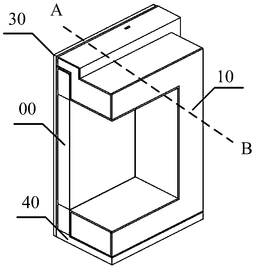
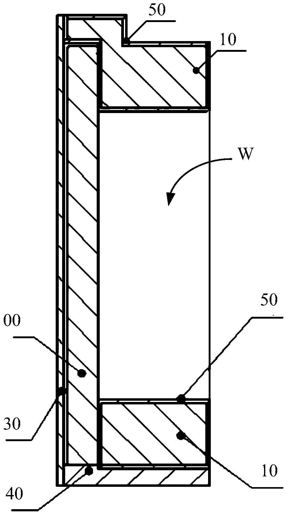
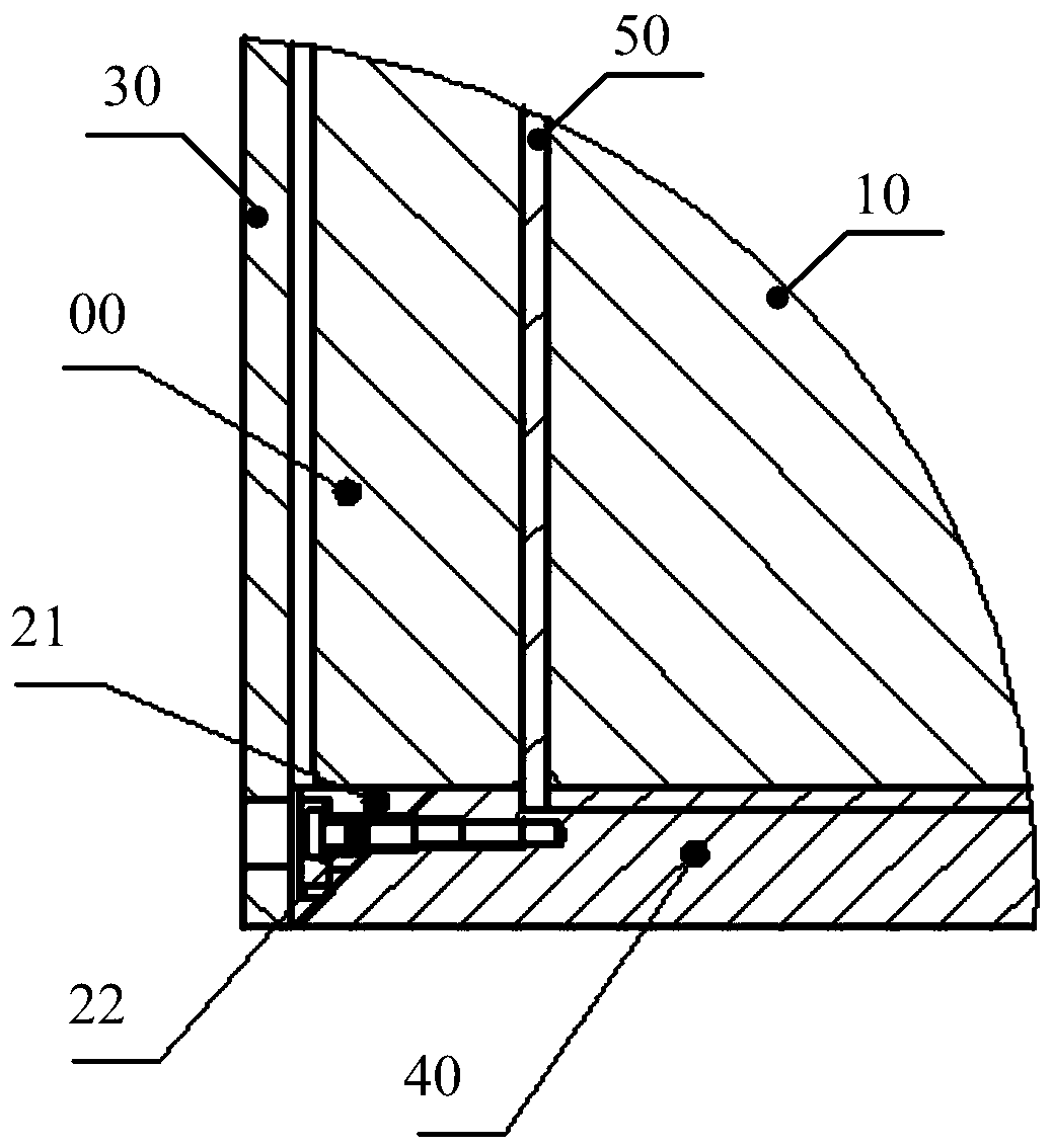
The present invention provides a mounting structure for a flat panel detector, comprising: a shielding assembly for shielding rays; In the shielded space: a first adjustment component is arranged on one side below the bottom edge of the flat panel detector, and is used to adjust the levelness of the flat panel detector. The first adjustment component is used to ensure the position accuracy of the flat panel detector after installation, especially the levelness of the horizontal detector. By adjusting the levelness of the flat panel detector, it can ensure that the rays penetrating the same layer of the detected object are received by the same row The row pixel array is received to avoid imaging errors. Using the installation structure to install the flat panel detector can facilitate installation and subsequent maintenance, and can also ensure imaging accuracy.

Description

technical field [0001] The invention relates to the technical field of radiation flat panel detector imaging, in particular to an installation structure for a flat panel detector. Background technique [0002] In recent years, radiation detection imaging technology has been widely used in various fields such as radiation medicine and non-destructive testing. High-energy X-rays have different attenuation when they penetrate objects of different materials and thicknesses, that is, the intensity of radiation received by the detector is also different. Therefore, it can According to the intensity of rays received by different positions of the detector, the internal structure characteristics of the detected object can be obtained. [0003] The commonly used detector is a flat-panel detector. X-rays are first converted into visible light by a dielectric material, then the visible light signal is converted into an electrical signal by a photosensitive element, and finally the analo...

Claims


Application Information

Patent Timeline
Patent Type & Authority Patents(China)
IPC IPC(8): G01N23/00
Inventor 卓立伟史戎坚邢全承刘林阮玉芳刘鹏浩
Owner INST OF HIGH ENERGY PHYSICS CHINESE ACAD OF SCI
Learn More