Adaptive time-delay feedback control micromachined gyroscope system

A technology of micro-mechanical gyroscope and feedback control, applied in gyroscope/steering sensing equipment, gyroscope effect for speed measurement, instrument and other directions, can solve the problem of system stability reduction and possible bifurcation and chaos, system damping complexity, stability Higher performance requirements and other issues, to achieve the effect of improving detection accuracy, adaptability and stability, and improving anti-interference ability

Inactive Publication Date: 2017-11-03
SHANGHAI INST OF TECH
View PDF4 Cites 0 Cited by
  • Summary
  • Abstract
  • Description
  • Claims
  • Application Information

AI Technical Summary

Problems solved by technology

On the other hand, the comb capacitor will complicate the system damping and show nonlinearity, so it is necessary to adopt vacuum packaging method to reduce the nonlinear influence of air damping
The nonlinear factors in the system (mainly stiffness nonlinearity and damping nonlinearity) may reduce the stability of the system and may cause complex dynamic behaviors such as bifurcation and chaos, especially for stability under complex working conditions. High performance requirements; time-delay velocity feedback control method and time-delay displacement feedback control method are widely used in academia and engineering fields to suppress the complex dynamic behavior of the system and improve the stability of the system, but in the non- In linear research, there are few methods of using time-delay feedback control to improve stability. Therefore, this patent mainly focuses on the application research of this theoretical method, and extends the theoretical method of time-delay feedback control to the control engineering application of resonant micro gyroscope systems. middle

Method used


Image

  • Adaptive time-delay feedback control micromachined gyroscope system
  • Adaptive time-delay feedback control micromachined gyroscope system
  • Adaptive time-delay feedback control micromachined gyroscope system

Examples


Embodiment Construction

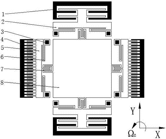
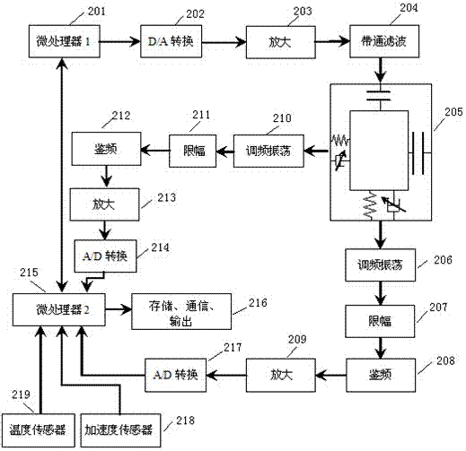
[0018] The self-adaptive time-delay feedback control micromechanical gyroscope system of the present invention, especially the time-delay feedback control of the electrostatically driven resonant micromechanical gyroscope, the electrostatic comb drive and the electrostatic comb capacitance and parallel plate capacitance are jointly detected, including temperature Compensation and acceleration compensation and sensitive direction amplitude feedback, through the frequency amplitude and waveform modulation of the driving voltage by the microprocessor.

[0019] figure 1 Shown is a schematic diagram of the structure of a single resonant mass indirectly connected, where the X-axis direction of the coordinates is the driving direction, the Y-axis direction is the detection direction, Ωz is the input angular velocity direction, 1 is the detection direction parallel plate capacitor fixed plate, and 2 is the parallel plate Capacitive movable plate, the sensitive direction adopts paralle...


PUM


Abstract

The invention relates to a self-adapted time lag feedback control micromechanical gyroscope system. A single-resonance mass block in a micromechanical gyroscope is used for detecting direction amplitude detection feedback and driving voltage in a driving direction, and driving waveform modulation to realize intelligent self-adapted control, so that the stability and precision of the gyroscope are improved. According to the system, two microprocessors are used for carrying out driving voltage waveform modulation, frequency modulation and calculation, detection, sampling and feedback. The accelerated speeds, the temperatures, and the angular speeds of the environment of the system are detected, feedback is made, and a drive is adjusted in time by the system according to the changes of environment characteristics, so that the system is stable and controllable to operate, and the intelligent self-adapted detection aim is realized; compared with a traditional driving detection system, the stability and the adaptive capacity to complicated conditions of the system can be remarkably improved; and the detection precision and stability can be greatly improved under the same hardware precision condition.

Description

technical field [0001] The invention relates to a micro-mechanical gyroscope, in particular to an adaptive time-delay feedback control micro-mechanical gyroscope system. Background technique [0002] The micromechanical gyroscope is a micro inertial sensor that uses the Coriolis effect to detect the angular velocity of a rotating object. Micromechanical gyroscopes prepared by microelectronic machining technology are widely used in aerospace, military, automotive, and consumer electronics products due to their low cost, small size, light weight, low power consumption, simple structure and process, and suitable for mass production. and other fields. Resonant micromachined gyroscope is a typical micromachined gyroscope with symmetrical structure, which is widely used in engineering. At present, the accuracy and stability of micro-mechanical gyroscopes are limited to a certain extent due to the processing errors of micro-gyroscopes, the inherent characteristics of materials, a...

Claims


Application Information

Patent Timeline
Patent Type & Authority Patents(China)
IPC IPC(8): G01C19/5776
CPCG01C19/5776
Inventor 尚慧琳张涛武云鹏衡博李伟阳宋书峰文永蓬
Owner SHANGHAI INST OF TECH
Why Eureka
Try Eureka