
Splicing measurement method for two sections of profiles of large-caliber optical aspheric element

A measurement method and aspheric surface technology, applied in the direction of measurement devices, optical devices, instruments, etc., can solve problems such as the lack of alignment solutions for splicing algorithms

Active Publication Date: 2015-05-06
XIAMEN UNIV
View PDF6 Cites 9 Cited by
  • Summary
  • Abstract
  • Description
  • Claims
  • Application Information

AI Technical Summary

Problems solved by technology

Jia Lide et al. (Jia Lide et al. Multi-segment splicing measurement method for high-steep conformal optical mirrors [J]. China Mechanical Engineering, 2009, 20(10): 1159-1162) proposed a method based on multi-segment splicing for high-steep conformal optical mirrors. Coordinate measurement method, but does not give the corresponding stitching algorithm and the solution to the alignment of overlapping areas in coordinate stitching measurement

Method used


Image

  • Splicing measurement method for two sections of profiles of large-caliber optical aspheric element
  • Splicing measurement method for two sections of profiles of large-caliber optical aspheric element
  • Splicing measurement method for two sections of profiles of large-caliber optical aspheric element

Examples


Embodiment Construction

[0041] The following embodiments will further illustrate the present invention in conjunction with the accompanying drawings.

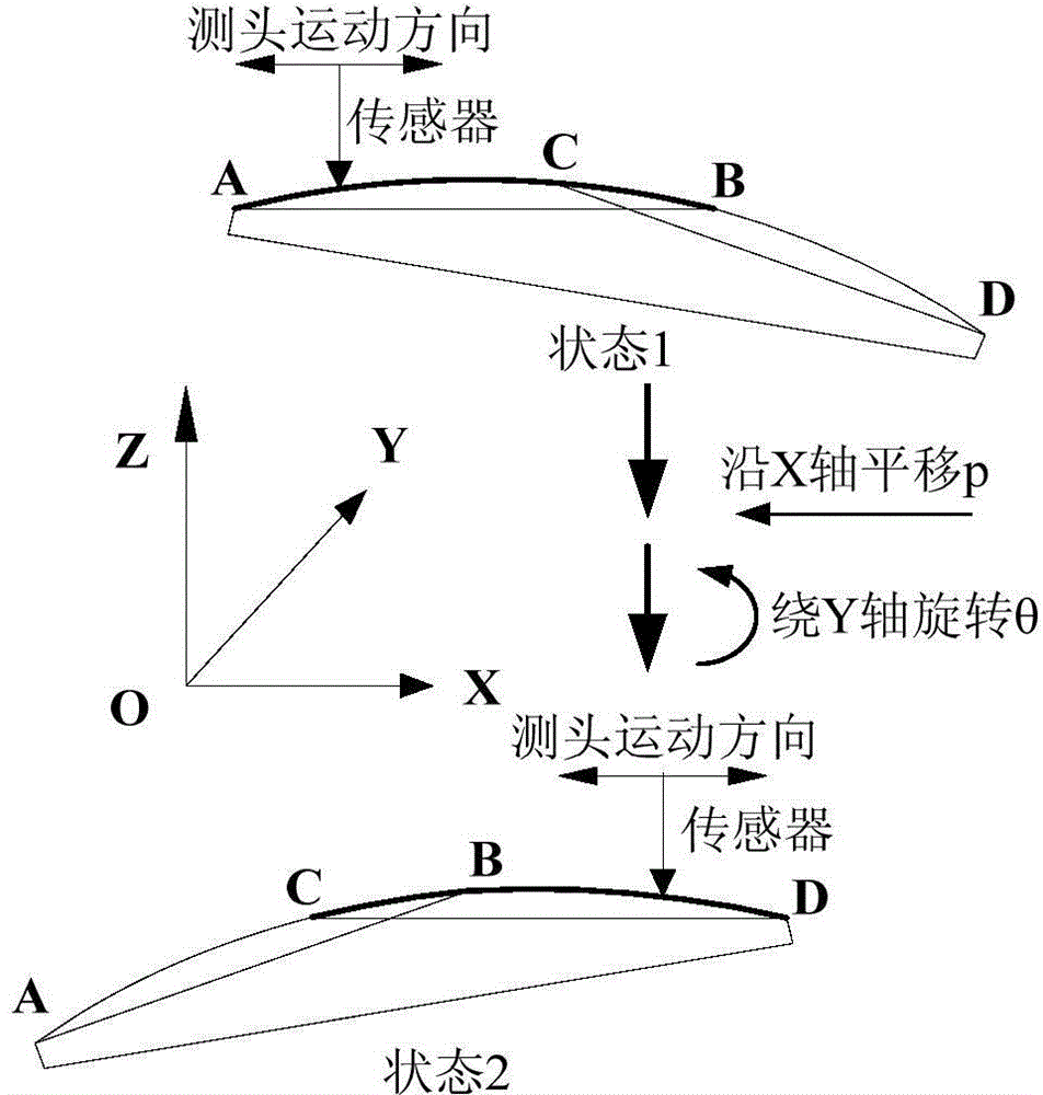
[0042] Such as figure 1 As shown, the surface profile of the measured workpiece is divided into AB segment and CD segment. The X direction is the horizontal movement direction of the profiler sensor, and the Z direction is the vertical measurement direction of the profiler sensor. First, measure the profile of segment AB in state 1; then translate and rotate the workpiece around the coordinate axis to state 2, so that the workpiece returns to the range of the sensor, and measure the profile of segment CD; and ensure that there is a certain overlapping area between the two profiles, It is the CB segment; finally, the segmented contours are stitched together through the overlapping area surface shape to reconstruct the surface shape profile of the workpiece under test. During the measurement process, due to the rotation and translation of the workpiec...


PUM


Abstract

The invention relates to non-optical spherical elements, in particular to a splicing measurement method for two sections of profiles of a large-caliber optical aspheric element. The splicing measurement method includes providing a method of aligning data points of an overlapped area on the basis of a principle that radius of curvature is unchanged; building a preliminary optimized mathematic model for twp-section surface figure profile splicing according to a multibody system kinetic theory, a slope difference value and an inversion method; according to a simulation result of the preliminary splicing mathematic model, performing linear least square fitting on preliminary splicing errors, removing accumulated errors, and providing a final two-section splicing optimized algorithm. Experiments in which a Taylor Hobson contourgraph and an auxiliary measuring clamp are utilized to measure planar optical elements of 150mm and data processing by using the splicing optimized algorithm are performed, and results of the experiments show that maximum standard deviation of the splicing errors is 0.868 micrometer, and high-accuracy surface figure detection needs of optical elements at a grinding stage can be met.

Description

technical field [0001] The invention relates to an aspheric element, in particular to a two-stage contour splicing measurement method for a large-diameter optical aspheric element. Background technique [0002] The use of large-aperture aspheric elements in the optical system can effectively correct aberrations, improve image quality, reduce the number of optical elements, thereby reducing the size and weight of the optical system, and greatly improving the optical performance of the optical system or instrument. Therefore, large-aperture aspheric components are increasingly being used in space optics, military, high-tech civilian and other fields. However, aspheric profile measurement equipment is mainly monopolized by foreign countries, and large-aperture profile measurement equipment is either expensive or difficult to obtain, so the improvement of processing accuracy and efficiency of large-aperture aspheric optical components has been restricted to a considerable extent...

Claims


Application Information

Patent Timeline
IPC IPC(8): G01B21/20
CPCG01B11/24
Inventor 杨平叶世蔚王振忠郭隐彪
Owner XIAMEN UNIV
Learn More