Rotational flow water film cooling type combustion chamber

A technology of combustion chamber and film cooling, which is applied in the direction of combustion chamber, continuous combustion chamber, combustion method, etc., can solve the problems of combustion chamber and high-temperature combustion chamber that do not allow oxygen, and achieve simple structure, easy processing and production and popularization and use , the effect of lowering the temperature

Inactive Publication Date: 2015-05-06
CHENGDU ENGINE GROUP
View PDF5 Cites 3 Cited by
  • Summary
  • Abstract
  • Description
  • Claims
  • Application Information

AI Technical Summary

Problems solved by technology

[0003] The purpose of the present invention is to overcome the deficiencies of the prior art and provide a swirling water film cooling combustor to solve the cooling problem of the combustor and high temperature combustor where oxygen is not allowed in the exhaust gas

Method used


Image

  • Rotational flow water film cooling type combustion chamber
  • Rotational flow water film cooling type combustion chamber
  • Rotational flow water film cooling type combustion chamber

Examples


Embodiment Construction

[0019] The swirling water film cooling type combustion chamber of the present invention will be further described below by means of embodiments and in conjunction with the accompanying drawings.

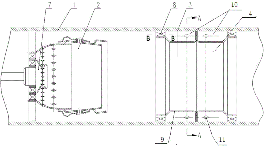
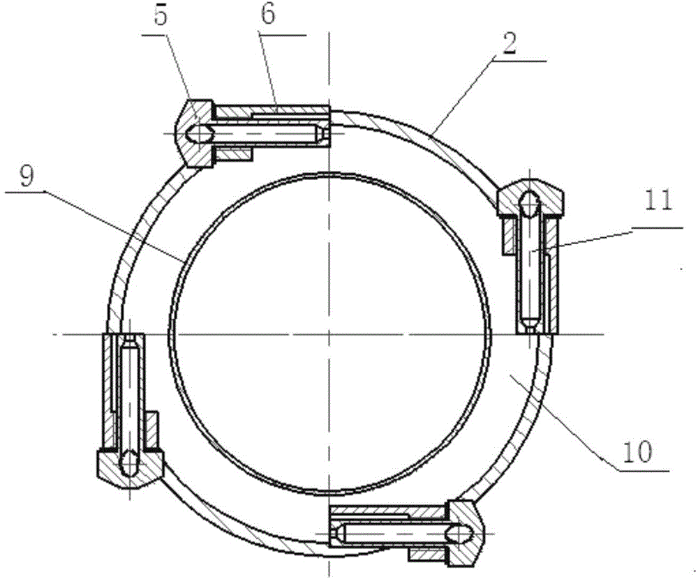
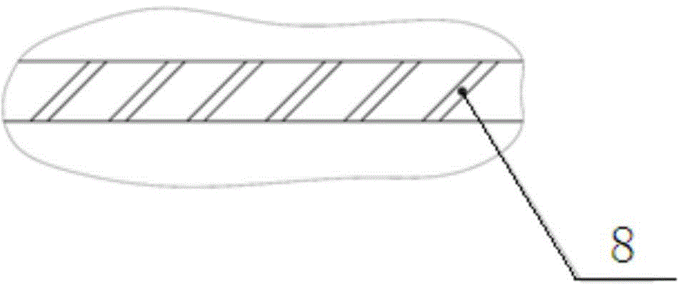
[0020] The swirling water film cooling combustor in this embodiment is used for oil drilling, and its structure is as follows figure 1 , figure 2 As shown, it includes a chamber wall 1, a flame tube head 2 installed in the combustion chamber, a first swirler 3 and a second swirler 4; the flame tube head has a premixing chamber 7, and the first swirler The first cyclone 3 and the second cyclone 4 have the same structure, and both are composed of a cylinder 9, a nozzle 5, a mounting seat 6 and a swirl vane 8. The outer surface of the cylinder 9 and the inner surface of the chamber wall 1 are closed at one end, An annular body water chamber 10 with one end open, swirl blades 8 are installed at the opening end of the annular body water chamber, there are 4 nozzles 5, and the number of ...


PUM


Abstract

A rotational flow water film cooling type combustion chamber comprises a chamber wall, a flame tube head and two hydrocyclones, wherein the flame tube head is mounted in an inner cavity of a combustion chamber body, and the two hydrocyclones enable water input externally to form a rotating water film attached to the inner surface of the chamber wall. The flame tube head is provided with a premixing chamber. The hydrocyclones are located behind the flame tube head and spaced from the flame tube head. Each hydrocyclone is composed of a barrel, spray heads, mounting bases and swirl blades, wherein the outer surface of the barrel and the inner surface of the chamber wall define an annular water cavity, one end of the annular water cavity is closed, and the other end of the annular water cavity is open; the swirl blades are mounted at the open end of the annular water cavity; the number of the spray heads is 2-4, the number of the mounting bases is the same as that of the spray heads, the spray heads are mounted on the chamber wall through the mounting bases, water inlet holes of the spray heads are communicated with the annular water cavity, and the axes of all the spray heads are located in the tangential direction of the chamber wall.

Description

technical field [0001] The invention relates to the technical field of cooling of a high-temperature combustion chamber, in particular to a newly created swirl water film cooling type combustion chamber. Background technique [0002] The combustion chamber usually adopts the method of film cooling, but for the combustion chamber that requires all the air in the combustion chamber to be burned, and the exhaust gas does not allow oxygen, as well as the high-temperature combustion chamber, the film cooling is not suitable because there is no Excess air is used for film cooling, and the outlet temperature of the high-temperature combustion chamber is very high (taking natural gas as an example, the outlet temperature of the combustion chamber can reach 2050°C), and the use of film cooling cannot effectively protect the chamber wall from being burned. Contents of the invention [0003] The purpose of the present invention is to overcome the deficiencies of the prior art and pro...

Claims


Application Information

Patent Timeline
Patent Type & Authority Applications(China)
IPC IPC(8): F23R3/58
Inventor 温良荣周莉莉方德胜陈静谢鹏玲李海萍彭亮刘健莫学明刘建
Owner CHENGDU ENGINE GROUP
Why Eureka
Try Eureka