Vibration absorber

A technology for shock absorbers and automobile shock absorption, which is applied in the direction of shock absorbers, shock absorbers, springs/shock absorbers, etc., and can solve problems such as shock absorbers and car bumps

Active Publication Date: 2015-05-06
ANHUI WEIWEI RUBBER PARTS GRP
View PDF6 Cites 0 Cited by
  • Summary
  • Abstract
  • Description
  • Claims
  • Application Information

AI Technical Summary

Problems solved by technology

[0008] The purpose of the present invention is to provide a shock absorber to solve the technical problem of automobile bumps caused by the original shock absorber being too hard or too soft

Method used


Image

  • Vibration absorber
  • Vibration absorber
  • Vibration absorber

Examples


Embodiment 1

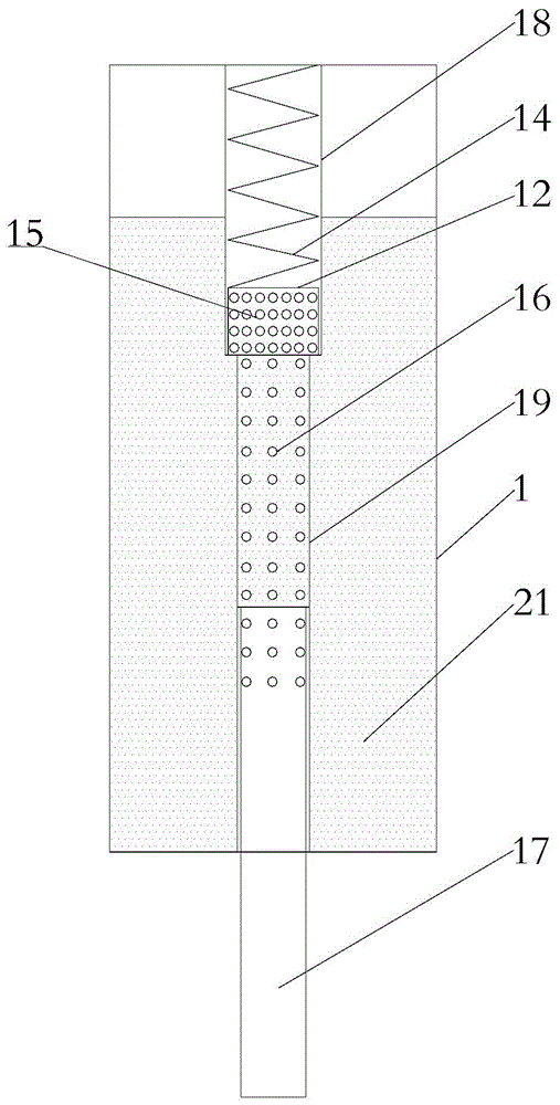
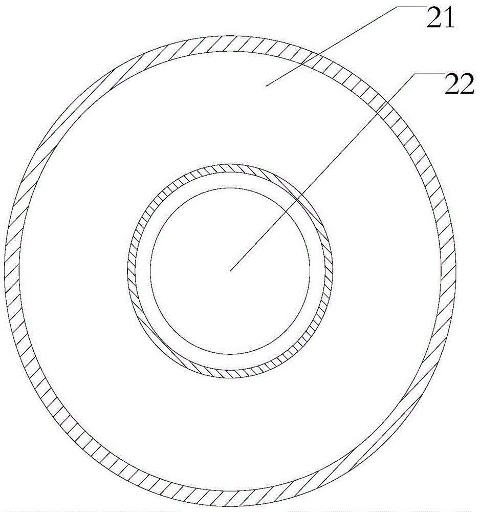
[0064] Such as figure 1 and figure 2 , a shock absorber is provided in an embodiment of the present invention, and the shock absorber includes a vertically arranged master cylinder 1; There is a gap between the cylinders of the layer, forming the main cylinder outer chamber 21; the inner cylinder is hollow, forming the master cylinder inner chamber 22; the cylinder of the inner layer is divided into the first inner cylinder part 18 located above and The second inner cylinder part 19 located below, the outer diameter of the first inner cylinder part is larger than the outer diameter of the second inner cylinder part; wherein:

[0065] The inner cavity of the master cylinder is provided with an active piston rod 17, and the other end of the active piston rod passes through the master cylinder for connection with the wheel;

[0066] A floating piston 12 is arranged above the active piston rod, the floating piston is located in the first inner cylinder, and an auxiliary spring...

Embodiment 2

[0071] Embodiment 2 also provides a shock absorber. This embodiment is a further improvement on the basis of Embodiment 1. The technical solution described in Embodiment 1 also belongs to this embodiment. The technical solution described in Embodiment 1 does not Repeat the description again.

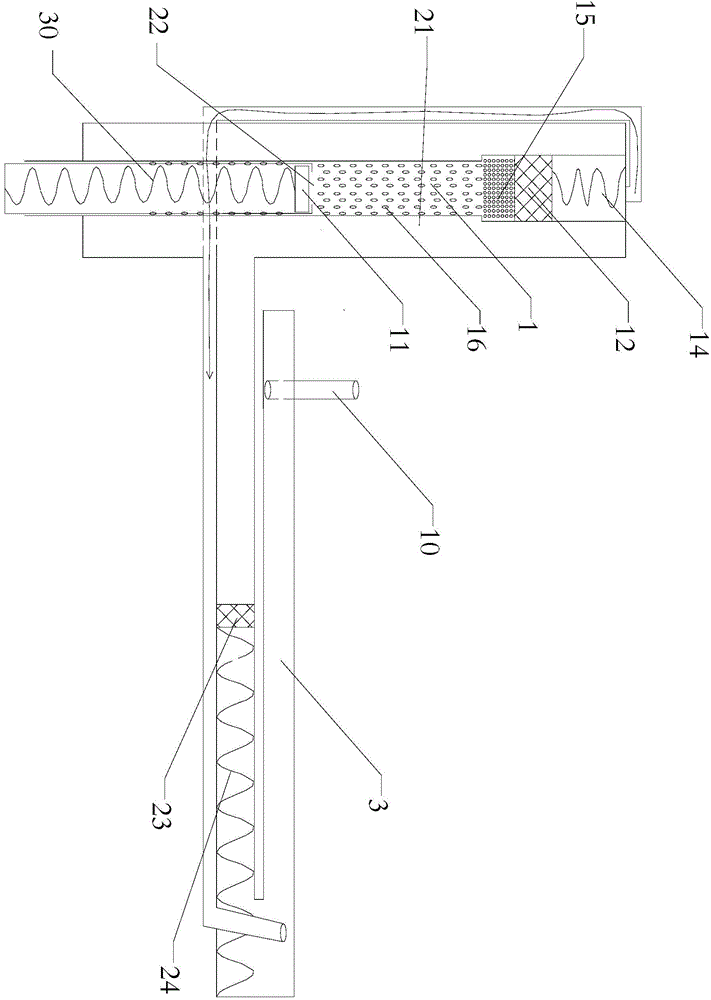
[0072] Such as image 3 As shown, a shock absorber is provided in the embodiment of the present invention. The shock absorber also includes an auxiliary cylinder 2 and a normal pressure cylinder 3 communicating with the outside world. The normal pressure cylinder 3 is located in the auxiliary cylinder 2 Above; the cavity between the floating piston 12 and the top of the master cylinder communicates with the normal pressure cylinder, and the outer cavity 21 of the master cylinder communicates with the normal pressure cylinder; the active piston rod is hollow, and its upper end part The opening is provided with a main piston 11 inside, and a main spring 30 is provided between the main pis...


PUM


Abstract

The invention provides a vibration absorber and relates to the field of vibration absorption equipment. The vibration absorber comprises a main cylinder, wherein the main cylinder comprises a main cylinder outer cavity and a main cylinder inner cavity; a cylinder body of the inner layer is divided into a first inner cylinder part and a second inner cylinder part located on the lower side; the outer diameter of the first inner cylinder part is greater than the outer diameter of the second inner cylinder part; a driving piston rod is arranged in the main cylinder inner cavity; one end of the driving piston rod penetrates through the main cylinder and is connected with a wheel; a floating piston is arranged on the upper side of the driving piston rod; a secondary spring is arranged between the floating piston and the top of the main cylinder; a cavity between the driving piston rod and the floating piston rod is filled with liquid; a plurality of side holes are formed in the side wall of the cylinder body of the inner layer and are divided into a dense hole region and a sparse hole region; the dense hole region is located on the first inner cylinder part and the sparse hole region is located on the second inner cylinder part; the interval distance among the side holes of the sparse hole region is greater than the interval distance among the side holes of the dense hole region. With the adoption of the vibration absorber, the technical problem of a traditional technology that an automobile body obviously jumps when an automobile meets a concave-convex road surface is solved.

Description

technical field [0001] The invention relates to the field of shock absorbing equipment, in particular to a shock absorber. Background technique [0002] In various vehicles such as automobiles, most of them are equipped with shock absorbers, the purpose of which is to reduce the shock and improve the stability of the vehicle body. [0003] At present, there are many automobile suspension damping technologies, all of which are aimed at comfort and stability. Comfort depends on the compression coefficient of the spring. A spring with a small compression coefficient is comfortable and is commonly referred to as a soft spring. However, the driving stability is poor, and the center of gravity of the vehicle will move outwards and rollover easily on curves, and the unbalanced passenger ride will cause the vehicle body to tilt to the passenger's passenger side. Therefore, the current shock absorber can only put safety first, and then take comfort into consideration. Therefore, a...

Claims


Application Information

Patent Timeline
Patent Type & Authority Applications(China)
IPC IPC(8): F16F13/00
CPCF16F13/002
Inventor 畅建坤
Owner ANHUI WEIWEI RUBBER PARTS GRP
Why Eureka
Try Eureka