
Steel beam positioning adjustment device

A positioning adjustment and steel beam technology, which is applied in construction, building structure, and building material processing, can solve the problems of low adjustment accuracy and difficult adjustment, and achieve the effects of convenient use, improved installation accuracy, and improved stability

Active Publication Date: 2016-08-31
ZHENGZHOU NO 1 CONSTR ENG GRP
View PDF12 Cites 1 Cited by
  • Summary
  • Abstract
  • Description
  • Claims
  • Application Information

AI Technical Summary

Problems solved by technology

[0003] The purpose of the present invention is mainly to solve the technical problems of difficult adjustment and low adjustment accuracy in the traditional steel beam installation process, and to provide a steel beam positioning adjustment device

Method used


Image

  • Steel beam positioning adjustment device
  • Steel beam positioning adjustment device
  • Steel beam positioning adjustment device

Examples


Embodiment 1

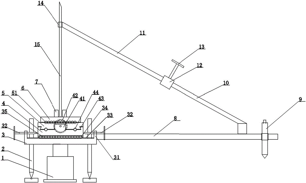
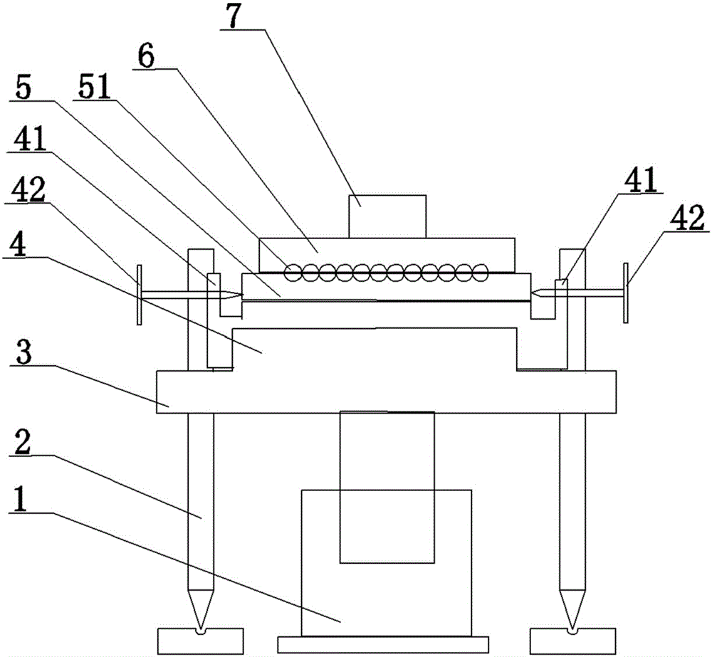
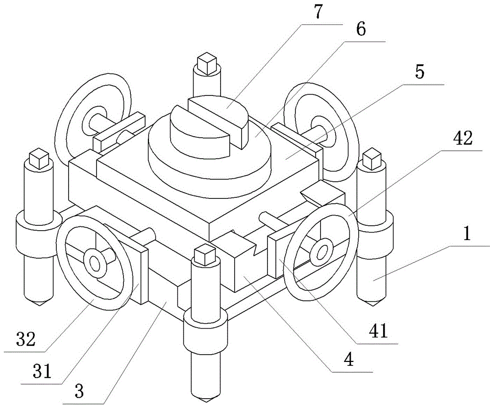
[0012] Embodiment 1: as Figure 1 ~ Figure 3 As shown, a steel beam positioning adjustment device is provided. The lower slider 3 has a square structure, and threaded holes are respectively provided at the top corners around it, and four horizontal adjustment screw screws 2 are installed on the vertical threads respectively. The bottom center of the bottom is vertically connected with a hydraulic jack 1. After adjusting the hydraulic jack 1 to make the adjustment platform reach a suitable height, then rotate each horizontal adjustment screw 2 to land, and adjust to realize the level. A level detector can be arranged at any suitable position of the lower slider 3 or the middle slider 4 or the upper slider 5 or the turntable 6, for example, a bubble type level detection tube is used.

[0013] The middle slider 4 and the lower slider 3 are slidably matched in the weft direction, and a weft adjustment knob 32 is arranged between the lower slider 3 and the middle slider 4 . The s...

Embodiment 2

[0017] Embodiment 2: can refer to figure 1 , provides another steel beam positioning adjustment device, the main structure is the same as that of embodiment 1, the difference is: the lower slider 3 can be circular or square, but a section of its outer side is designed to be circular, and its bottom The horizontal adjustment leading screw 2 can be four symmetrically, also can be three evenly distributed. A rotatable overcoat at the same height is sheathed on the outer side of the circular part, and the auxiliary cross bar 8 is fixedly connected to the overcoat so that the auxiliary cross bar 8 can rotate along the lower slider 3 .

[0018] This device has the functions of warp adjustment, weft adjustment, height adjustment, angle adjustment, rotation adjustment and so on. Steel ball row sliding technology is adopted. As shown in the figure, height adjustment hydraulic jack 1, level adjustment wire (support), lower slider 3, middle slider 4, upper slider 5, turntable 6, etc. ...


PUM


Abstract

The invention discloses a steel beam locating and adjusting device which comprises a hydraulic jack, an adjusting platform and a locating clamp. The adjusting platform comprises a lower slide block, a middle slide block and an upper slide block, wherein the lower slide block, the middle slide block and the upper slide block are sequentially in slide fit with each other. At least three horizontal adjusting lead screws and the hydraulic jack are vertically arranged at the periphery of the lower slide block in a threaded mode, a rotating disk is arranged in the center of the upper portion of the upper slide block, the steel beam locating clamp is arranged in the center of the upper portion of the rotating disk, and a steel beam can be vertically fixed into the clamp. A height adjusting rod and an angle adjusting fixed rod are vertically arranged at the tail end of an auxiliary horizontal rod in a threaded mode, and the tail end of the auxiliary horizontal rod is fixedly buckled with the steel beam through a buckle. The steel beam locating and adjusting device has the effect on installing and adjusting steel webs, improves steel web installing accuracy and saves labor and materials. The steel beam locating and adjusting device also has the functions of longitudinal adjustment, latitudinal adjustment, height adjustment, angle adjustment and rotation adjustment. In addition, the steel beam locating and adjusting device is convenient to use, good in trying effect and good in reputation.

Description

technical field [0001] The invention belongs to the technical field of building installation and construction, and in particular relates to a steel beam positioning adjustment device. Background technique [0002] In the traditional steel beam installation and construction process, the installation and adjustment of the steel beam are manually adjusted. Due to the weight of the steel beam, the installation and adjustment are difficult and the adjustment accuracy is not high. After the adjustment, it is easy to deform due to various factors, which affects the construction quality. produced many adverse effects. As a result, the construction is difficult, the efficiency is low, and even some rework occurs, which increases the construction cost. Contents of the invention [0003] The purpose of the present invention is mainly to provide a steel beam positioning adjustment device to solve the technical problems of difficult adjustment and low adjustment accuracy in the tradit...

Claims


Application Information

Patent Timeline
Patent Type & Authority Patents(China)
IPC IPC(8): E04G21/18
Inventor 郭向永雷霆李遐李建锋韦纯明王前林董艳臣陈晓阳陈喆时媛媛张俊杰
Owner ZHENGZHOU NO 1 CONSTR ENG GRP
Learn More