
3D printer working platform and positioning method thereof

A 3D printer and working platform technology, applied in the field of 3D printing, can solve the problems of increased printing effect uncertainty, edge warping of printed products, and decline in the quality of printed products, so as to reduce the errors of misalignment and warping of printed products The effect of high efficiency, improved fixed stability, and uniform fixed force

Inactive Publication Date: 2015-05-06
BEIJING TIERTIME TECH
View PDF7 Cites 7 Cited by
  • Summary
  • Abstract
  • Description
  • Claims
  • Application Information

AI Technical Summary

Problems solved by technology

In 3D printing, the fixed stability and levelness of the working platform are the key steps in the pre-printing work and one of the important criteria for determining the quality of the printed product. If the levelness and fixed stability of a 3D printer working platform do not meet the requirements, it will be It will lead to a decline in the quality of the printed product, and if it is serious, it will cause the edge of the printed product to warp during the printing process, and the direct printing will fail
Because the printing substrate needs to be disassembled repeatedly, the stable fixing of the printing substrate and the printing substrate and the levelness of the printing substrate are important prerequisites for the finished product of the 3D printer. The clamping tool of the rail box, or the adjustable locks around it, the setting of this kind of fixing method cannot ensure the uniform fixing force of the upper printing substrate, and it is easy to cause the levelness of the printing substrate to drop. During the working process of the 3D printer, the printer The nozzle and the formed material are thickened by smearing, so the formed material will be stressed, and the upper printing substrate has the defect of insufficient fixing stability, resulting in more uncertainties in the final printing effect

Method used


Image

  • 3D printer working platform and positioning method thereof
  • 3D printer working platform and positioning method thereof
  • 3D printer working platform and positioning method thereof

Examples


Embodiment Construction

[0021] The structure of the present invention will be explained in detail below in conjunction with the accompanying drawings.

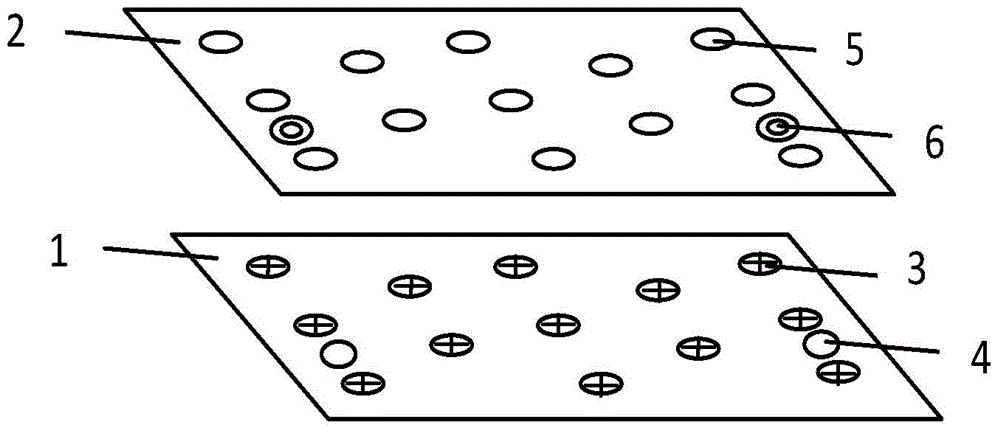
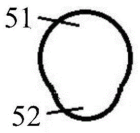
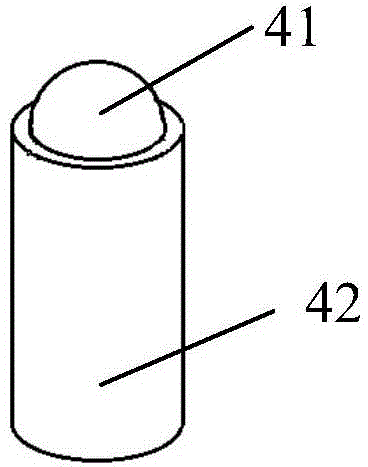
[0022] Such as figure 1 As shown, the working platform of a 3D printer provided by the present invention includes a printing base plate 1 and a printing base plate 2, wherein at least one positioning pin 3 and at least one stepped light-body positioning wave bead 4 are fixed on the printing base plate , the positions corresponding to the positioning pins and the step light body positioning beads on the printing substrate are respectively provided with pin holes 5 and positioning holes 6. Cooperate with the detachable connection of the printing bottom plate.

[0023] The working platform of a 3D printer provided by the present invention has a rectangular printing bottom plate. There are thirteen positioning pins, nine of which are evenly installed on the two diagonals of the rectangular printing base, and the other four are installed at the midpoint...


PUM


Abstract

The invention discloses a 3D printer working platform and a positioning method thereof. The 3D printer working platform comprises the following components: a printing under-plate and a printing base-plate, wherein the printing under-plate is fixedly connected with at least one positioning pin and at least one step light-body positioning bead, and pin holes and positioning holes are formed in positions on the printing base-plate, corresponding to the positioning pins and the step light-body positioning beads. The 3D printer working platform has the benefits that the printing base-plate is fixedly installed on the printing under-plate by the positioning pins and the step light-body positioning beads to realize fixed and uniform force on the printing base-plate plane, so as to satisfy requirement for the levelness of a printing platform while improving fixed stability of the printing base-plate to prevent moving of the printing base-plate in various directions when being stressed, thus effectively reducing error ratios of layer staggering and warping of printed products to realize high-quality product printing. The positioning method using the 3D printer working platform is simple to operate and convenient to dismantle.

Description

technical field [0001] The invention relates to the technical field of 3D printing, in particular to a working platform of a 3D printer and a positioning method thereof. Background technique [0002] 3D printing technology (or rapid prototyping technology) has developed rapidly because of its many advantages over the existing subtractive processing technology. In 3D printing, the fixed stability and levelness of the working platform are the key steps in the pre-printing work and one of the important criteria for determining the quality of the printed product. If the levelness and fixed stability of a 3D printer working platform do not meet the requirements, it will be It will lead to a decline in the quality of the printed product, and if it is serious, it will cause the edge of the printed product to warp during the printing process, and the direct printing will fail. [0003] The working platform is composed of upper and lower parts, one is the lower printing base plate, ...

Claims


Application Information

Patent Timeline
Patent Type & Authority Applications(China)
IPC IPC(8): B29C67/00B33Y30/00
Inventor 胡继荣金世振
Owner BEIJING TIERTIME TECH
Learn More