
motor

A technology of stator teeth and tooth sleeves is applied in the shape/style/structure of winding insulation, the shape/style/structure of magnetic circuit, and the static parts of magnetic circuit, etc., which can solve the problems of reduced motor efficiency and low motor slot full rate. , to achieve the effect of improving efficiency, improving slot full rate and saving cogging space

Active Publication Date: 2018-02-13
GREE ELECTRIC APPLIANCES INC +1
View PDF7 Cites 0 Cited by
  • Summary
  • Abstract
  • Description
  • Claims
  • Application Information

AI Technical Summary

Problems solved by technology

[0005] The purpose of the present invention is to provide a motor to solve the technical problems of low motor slot fullness and reduced motor efficiency in the existing poleless shoe structure

Method used


Image

  • motor
  • motor
  • motor

Examples


Embodiment Construction

[0029] The embodiments of the present invention will be described in detail below with reference to the accompanying drawings, but the present invention can be implemented in many different ways defined and covered by the claims.

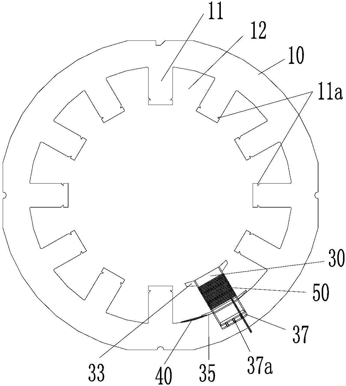
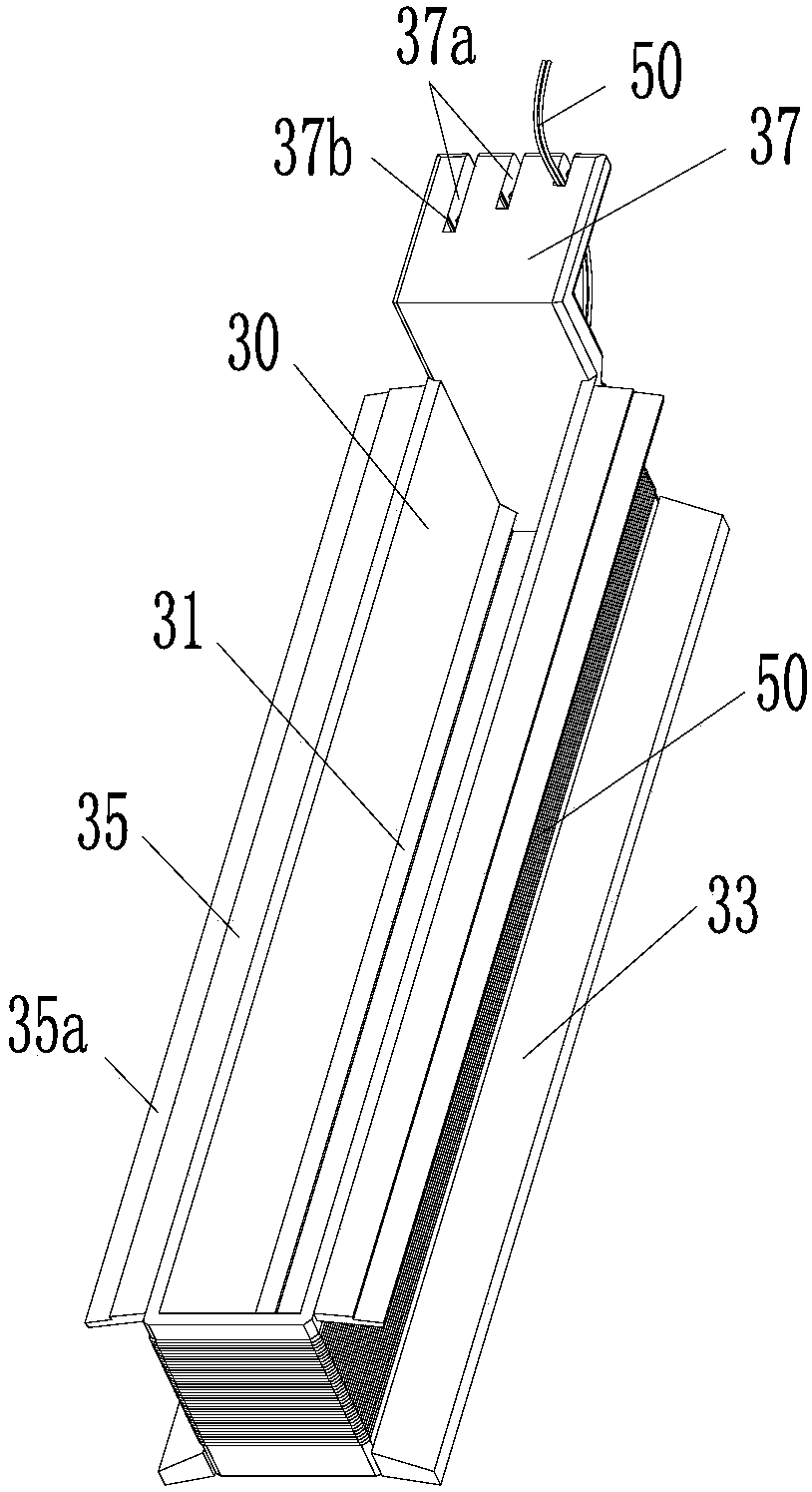
[0030] like Figure 2 to Figure 4 As shown, the present invention provides a motor, which includes: a stator 10 with stator teeth 11 ; a gear sleeve 30 sleeved on the outer circumference of the stator teeth 11 ; and a winding 50 wound on the outer circumference of the gear sleeve 30 . In the motor provided by the present invention, the gear sleeve 30 is sleeved on the outer circumference of the stator tooth 11, and then the winding 50 is wound on the outer circumference of the gear sleeve 30, which saves the tooth space occupied by the winding nozzle in the prior art, from Figure 5 It can be seen from the figure that the area of ​​the winding 50 wound in the tooth slot 12 can be increased by using the tooth sleeve 11, and the slot filling rate can ...


PUM


Abstract

The invention provides a motor. The motor comprises a stator, a gear sleeve, and windings, wherein the stator comprises stator teeth; the gear sleeve sleeves the periphery of the stator teeth; the winding is wound around the periphery of the gear sleeve. According to the motor provided by the invention, the gear sleeve sleeves the periphery of the stator teeth, and the windings are wound around the periphery of the gear sleeve, so that no winding mouth space needs to be reserved, the tooth space can be reduced, more windings can be wound inside the tooth space, the winding area can be enlarged, and the space factor of the stator and the motor efficiency can be improved.

Description

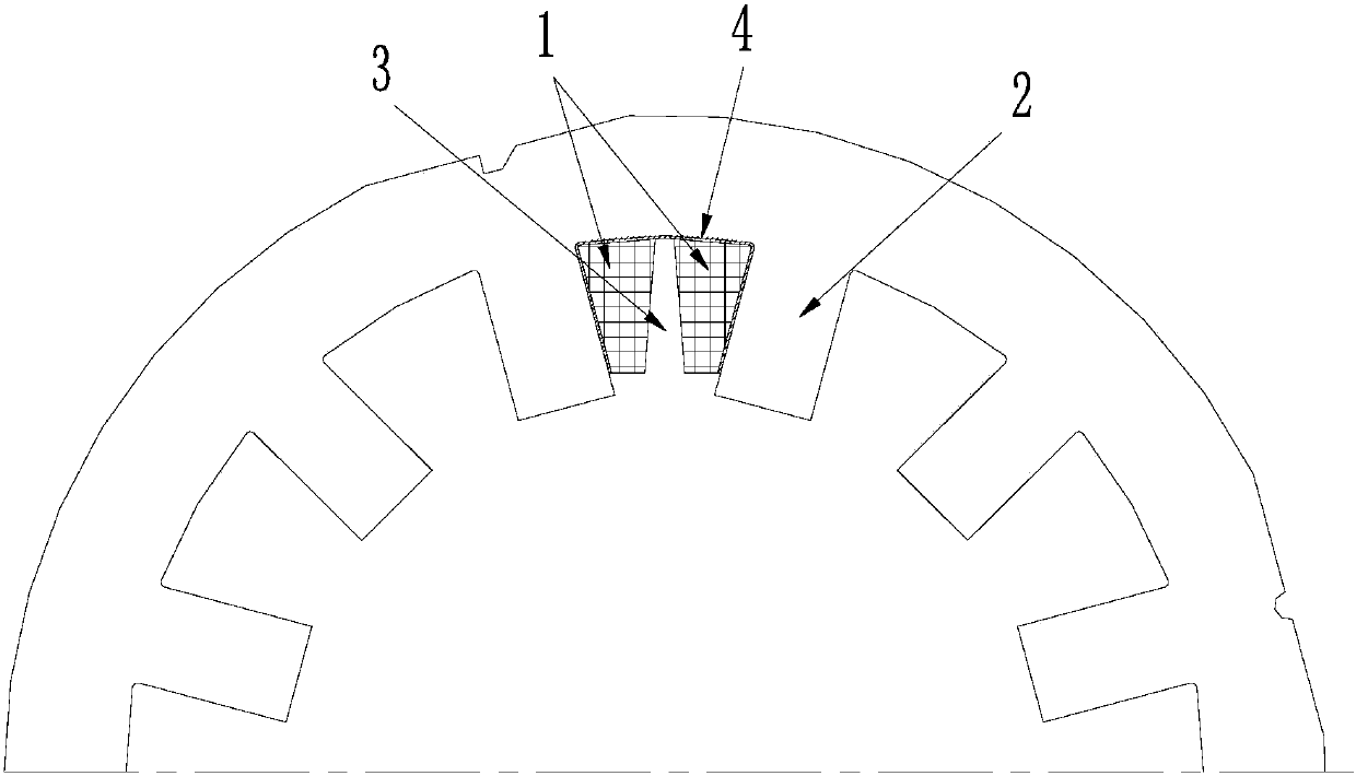
technical field [0001] The present invention relates to the technical field of motors, in particular, to a motor. Background technique [0002] The stator core in the existing motor usually has a pole shoe, which is the protrusion at the front end of the stator teeth. With pole pieces, the conductors in the stator slots are prevented from slipping out. [0003] However, with the development of motor technology, the magnetic circuit design of new motors such as switched reluctance motors, switched flux linkage motors, and magnetic levitation motors requires a poleless shoe structure. Currently, if figure 1 As shown, for a poleless stator, the winding 1 is usually wound directly to the outer circumference of the stator tooth 2. Since there is no pole shoe to limit the winding, the winding area cannot be too large, and the winding 1 must be trapezoidal to ensure that the winding 1 will not flow into the slot. slipped outside. Moreover, the reserved space 3 of the winding no...

Claims


Application Information

Patent Timeline
Patent Type & Authority Patents(China)
IPC IPC(8): H02K1/16
CPCH02K1/14H02K3/34
Inventor 童童陈东锁陈彬肖勇
Owner GREE ELECTRIC APPLIANCES INC
Learn More