Switchgear integrated in a modular smart grid

A smart grid and switchgear technology, applied in substation/switch layout details, substation/switchgear board/panel/desk, electrical components, etc., can solve the problem of excessively large switchgear, prone to rollover, and unreasonable structural design To achieve the effect of enhancing integration, optimizing weight ratio and facilitating installation

Active Publication Date: 2017-02-22
江苏德春电力科技股份有限公司
View PDF5 Cites 0 Cited by
  • Summary
  • Abstract
  • Description
  • Claims
  • Application Information

AI Technical Summary

Problems solved by technology

[0002] The smart grid is the intelligence of the power grid, also known as "grid 2.0", it is based on an integrated, high-speed two-way communication network, through advanced sensing and measurement technology, advanced equipment technology, advanced control methods And the application of advanced decision support system technology to achieve the goals of reliability, safety, economy, efficiency, environmental friendliness and safe use of the power grid. With the development of smart grid, smart grid and its high-voltage equipment are developing toward integration and modularization , with the development of the smart grid, the high-voltage equipment in the smart grid has higher and higher requirements on the overall size and strength, and the existing high-voltage equipment, such as switch cabinets, circuit breakers, etc. The side panel of the cabinet is installed by drilling holes. This installation method affects the weight ratio of the switch cabinet, which makes it prone to rollover, and also reduces the strength of the switch cabinet, causing the switch cabinet to be easily deformed. The switch cabinet used Due to the unreasonable structural design of circuit breakers and other devices, the switchgear is too large, which is inconvenient to install in the smart grid, which is not conducive to the development of smart grid integration and modularization

Method used


Image

  • Switchgear integrated in a modular smart grid
  • Switchgear integrated in a modular smart grid
  • Switchgear integrated in a modular smart grid

Examples


Embodiment Construction

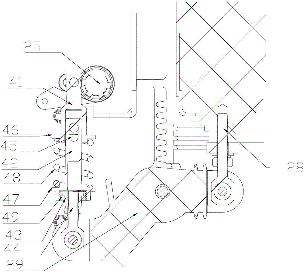
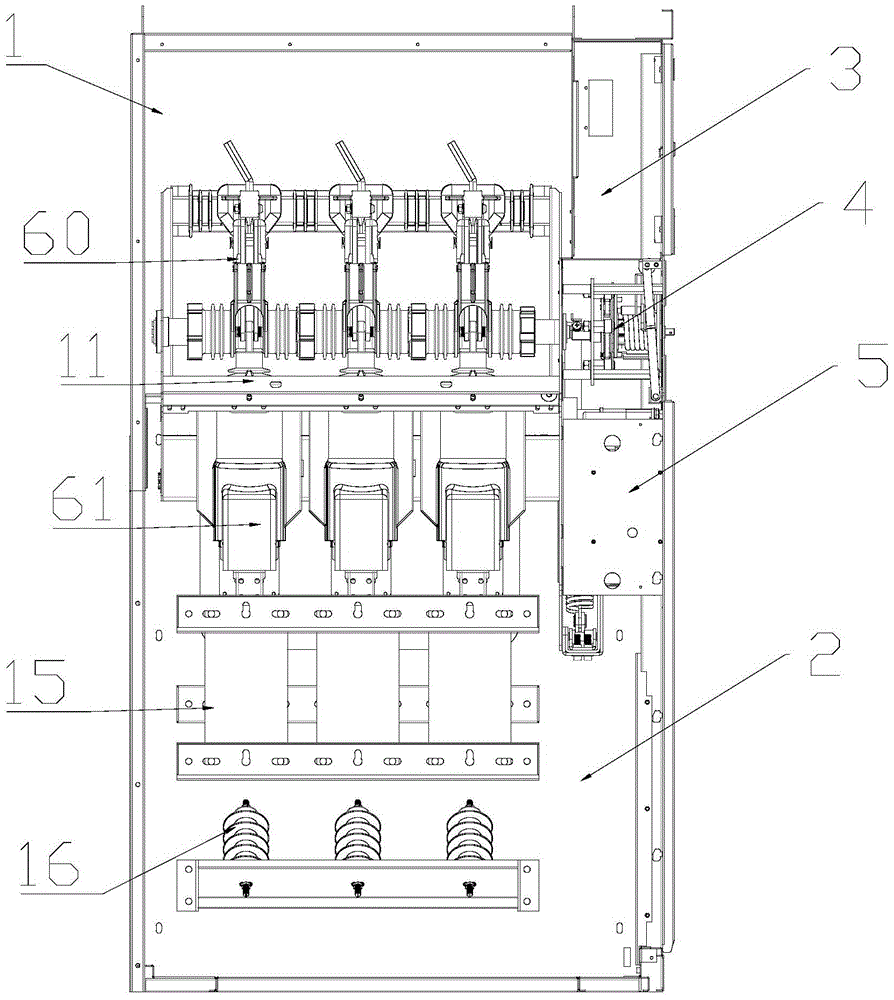
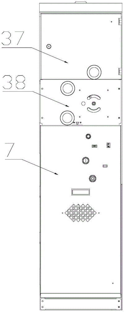
[0029] Depend on Figure 1 to Figure 9 It can be seen that the switch cabinet integrated in the modular smart grid of the present invention includes a cabinet body composed of an upper cabinet body 1 and a lower cabinet body 2, and a relay instrument room 3, an isolating switch operating mechanism 4, a circuit breaker, and a relay instrument room 3 arranged sequentially from bottom to top at the front end of the cabinet body. The device operating mechanism 5 and the lower cabinet door 7, the two sides of the lower cabinet body 2 are provided with two opposite side plates 8, the upper end of the side plate 8 is provided with a flange 9 bent into the cabinet, and the flange 9 is provided with a flange installation hole 10, and the insulation installation frame is fixedly installed on the flange 9, and the insulation installation frame is fixed on the left side plate 111 and the right side plate 112 fixedly connected with the flange 9. 111 and the front end plate 12 at the front ...


PUM


Abstract

The invention relates to a switch cabinet integrated to a modular smart power grid. The switch cabinet comprises a cabinet body which consists of an upper cabinet body and a lower cabinet body as well as a relay instrument room, an isolating switch operating mechanism, a circuit breaker operating mechanism and a lower cabinet door which are sequentially arranged at the front end of the cabinet body from bottom to top, wherein two opposite side plates are arranged on two sides of the lower cabinet body; an edgefold which is bent towards the interior of the cabinet body is arranged at the upper end of each of the side plates; edgefold mounting holes are formed in each of the edgefolds; an insulating mounting frame is fixedly mounted on the edgefolds, the insulating mounting frame consists of a front end plate, a rear end plate, an inlet wire insulating supporting piece, a left side plate and a right side plate; an isolating switch and a circuit breaker are mounted on the insulating mounting frame; a current transformer and a lightning arrester are further sequentially arranged from top to bottom below the circuit breaker in the lower cabinet body. The switch cabinet provided by the invention is high in integrated degree and small in size, so that development of the modular smart power grid is facilitated.

Description

technical field [0001] The invention relates to the field of high-voltage equipment for a modular smart grid, in particular to a switchgear integrated in a modular smart grid. Background technique [0002] The smart grid is the intelligence of the power grid, also known as "grid 2.0", it is based on an integrated, high-speed two-way communication network, through advanced sensing and measurement technology, advanced equipment technology, advanced control methods And the application of advanced decision support system technology to achieve the goals of reliability, safety, economy, efficiency, environmental friendliness and safe use of the power grid. With the development of smart grid, smart grid and its high-voltage equipment are developing toward integration and modularization , with the development of the smart grid, the high-voltage equipment in the smart grid has higher and higher requirements on the overall size and strength, and the existing high-voltage equipment, su...

Claims


Application Information

Patent Timeline
Patent Type & Authority Patents(China)
IPC IPC(8): H02B1/26H02B1/01H02B1/04
CPCH02B1/012H02B1/041H02B1/26
Inventor 王雯斐戚启忠许漫王国根
Owner 江苏德春电力科技股份有限公司
Why Eureka
Try Eureka