Multi-branch mobile terminal antenna and mobile terminal thereof
A mobile terminal antenna and mobile terminal technology, applied in the direction of antenna, antenna coupling, antenna support/installation device, etc., can solve the problems of not being able to reach low-frequency bandwidth, restricting low-frequency bandwidth, and small clearance end face, so as to increase independence and reduce Environmental requirements, the effect of improving joint bandwidth
- Summary
- Abstract
- Description
- Claims
- Application Information
AI Technical Summary
Problems solved by technology
Method used
Image
Examples
specific Embodiment approach 1
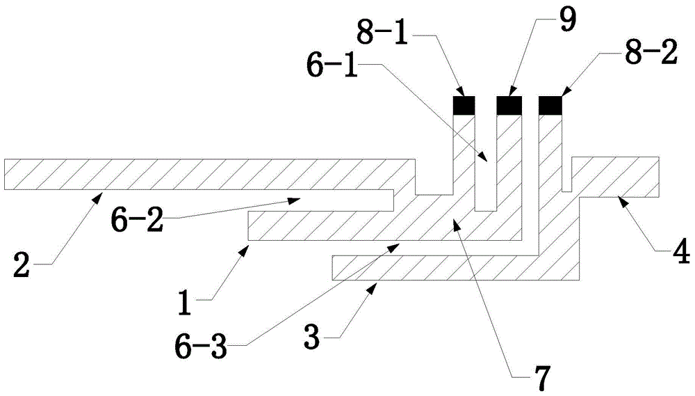
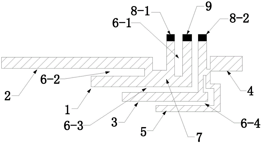
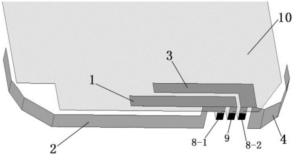
[0044] A mobile terminal using the above-mentioned multi-branch mobile terminal antenna. The mobile terminal includes a narrow border. When the multi-branch mobile terminal antenna is installed, the flat plate 7, the first ground terminal 8-1, the second ground terminal 8-2, and the feed terminal 9 are bent. After bending, the high-frequency radiation branch 1 and The first parasitic branch 3 is located in the clear end projection area on the terminal main board 10, the low-frequency radiation branch 2 extends along the top surface of the inner wall of the narrow border, and the second parasitic branch extends along the top surface of the inner wall of the narrow border.
[0045] The above-mentioned solution makes reasonable use of the clear end face and narrow side top face of the terminal, which not only satisfies the need for radiation to flow, but also flexibly adapts to the appearance design of the terminal. The antenna avoids the "G"-shaped structure, makes more reasonable ...
specific Embodiment approach 2
[0048] The high-frequency branch 1 and the first parasitic branch 3 are located in the projection of the clearance plane on the terminal main board 10. The low-frequency radiation branch 2 is a single trace and extends along the top surface of the narrow border; the second parasitic branch 4 It is a single trace that extends along the top surface of the narrow border. In the slot 6-3, a capacitor or capacitive element 11 is connected between the high-frequency radiation branch 1 and the first parasitic branch 3 to enhance coupling.
[0049] The high-frequency radiation branch 1 is a main high-frequency radiator, corresponding to a first resonance point.
[0050] The first parasitic branch 3 is an internal parasitic high-frequency radiator, which extends close to the first branch 1 and can be as long as required for actual debugging, corresponding to a second resonance point.
[0051] The second parasitic branch 4 is an external parasitic high-frequency radiator, corresponding to a t...
specific Embodiment approach 3
[0053] The high-frequency branch 1 and the first parasitic branch 3 are located in the projection of the clearance plane on the terminal main board 10. The low-frequency radiation branch 2 is a single trace and extends along the top surface of the narrow border; the second parasitic branch 4 It is a single trace that extends along the top surface of the narrow border. A coupling sheet 12 is provided above or below the slot 6-3 to enhance coupling. The coupling sheet is a metal sheet.
[0054] The high-frequency radiation branch 1 is a main high-frequency radiator, corresponding to a first resonance point.
[0055] The first parasitic branch 3 is an internal parasitic high-frequency radiator, which extends close to the first branch 1 and can be as long as required for actual debugging, corresponding to a second resonance point.
[0056] The second parasitic branch 4 is an external parasitic high-frequency radiator, corresponding to a third resonance point, and a weak coupling is for...
PUM
 Abstract
Description
Claims
Application Information
 - R&D
- Intellectual Property
- Life Sciences
- Materials
- Tech Scout
- Unparalleled Data Quality
- Higher Quality Content
- 60% Fewer Hallucinations
Browse by: Latest US Patents, China's latest patents, Technical Efficacy Thesaurus, Application Domain, Technology Topic, Popular Technical Reports.
© 2025 PatSnap. All rights reserved.Legal|Privacy policy|Modern Slavery Act Transparency Statement|Sitemap|About US| Contact US: help@patsnap.com


