a contactor

A technology of contactors and static contacts, which is applied in the direction of relays, electromagnetic relays, detailed information of electromagnetic relays, etc., can solve the problems of high production cost, troublesome wiring of static contacts, easy breakage of hooks, etc., and achieve low cost and convenient wiring Easy installation and structure

Active Publication Date: 2017-01-11
XIAMEN HONGFA ELECTRICAL SAFETY & CONTROLS CO LTD
View PDF5 Cites 0 Cited by
  • Summary
  • Abstract
  • Description
  • Claims
  • Application Information

AI Technical Summary

Problems solved by technology

[0003] In order to facilitate the connection between the static contact and other electrical components, the terminal assembly structure is usually installed on the body. The terminal assembly structure usually includes a terminal module and a terminal frame. The terminal module is installed on the body, and the terminal frame is installed on the terminal module. However, its disadvantages are: 1. The wiring of the static contacts is inconvenient. When the static contacts are wired, the wiring frame needs to be lifted for wiring, and the wiring of the static contacts is more troublesome.
Second, when the wiring frame is installed on the terminal module, it is difficult to accurately control the displacement range of the wiring frame
[0004] The wiring terminal module is installed on the body and the arc extinguishing chamber using a hook structure. The disadvantages of the hook installation structure are: 1. Since the wiring terminal module can be installed or removed, the wire is directly locked on the contact plate of the static contact. After multiple disassembly and assembly, the hook is easy to break
Second, when the terminal module is removed and used, it is impossible to install an insulating partition between the contact plates of the static contacts, making it impossible to prevent phase-to-phase short circuit
[0005] In order to install the static iron core, pin holes are usually provided on the contact support, and corresponding pin holes are provided on the static iron core. Then, the fixed pins are inserted into the two pin holes in sequence, and the static iron core is installed on the contact support. Its disadvantages are: 1. When the static iron core is released, the contact support is reset under the action of the reaction force spring, so that the contact support collides with the body, and because the contact support is relatively fragile, the contact support is easily damaged
Second, when the contact support moves under the action of the electromagnet, the side of the contact support will rub against the body, and the friction is surface-to-surface friction, which makes the contact support and the body wear more
Third, in order to prevent the fixing pin from falling off, it is often necessary to design a more complicated fixing structure to limit the fixing pin, and the structure is complicated and the cost is increased
[0006] In order to increase the auxiliary function of the contactor, functional auxiliary modules such as contact auxiliary modules and delay auxiliary modules are usually added. The mounting structure of the auxiliary contacts of the contactor usually includes: 1. The arc extinguishing chamber and the mounting structure are formed separately. An installation cavity is formed in the arc extinguishing chamber, and the hanging structure is inserted and installed in the installation cavity. The disadvantage is that two sets of molds need to be set up to produce the arc extinguishing chamber and the hanging structure respectively, and the production cost is relatively high; Install the arc extinguishing cover and integrally form a hanging structure on the arc extinguishing cover. The disadvantage is that because the arc extinguishing cover is integrally formed with a hanging structure, it is impossible to install contacts that will be exposed to the arc extinguishing chamber on the arc extinguishing cover. The protective cover that supports the cover affects the function expansion of the arc extinguishing cover. The contact support is easy to be accidentally touched, and the safety is not high

Method used


Image

  • a contactor
  • a contactor
  • a contactor

Examples


Embodiment Construction

[0083] The present invention will be described in detail below in conjunction with the accompanying drawings and specific embodiments.

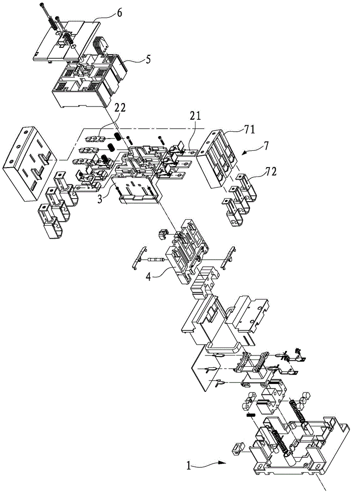
[0084] refer to Figure 1 to Figure 21 As shown, a contactor disclosed by the present invention includes a base 1 , a static contact 21 , a moving contact 22 , a body 3 , a contact support 4 , an arc extinguishing chamber 5 and an arc extinguishing cover 6 .

[0085] like figure 1 As shown, the static contact 21 is installed on the body 3, and the body 3 is installed on the base 1; the moving contact 22 is installed on the contact support 4, and the contact support 4 is movably installed in the body 3; the arc extinguishing chamber 5 is installed on On the body shell 3 , the arc extinguishing cover 6 is installed on the arc extinguishing chamber 5 .

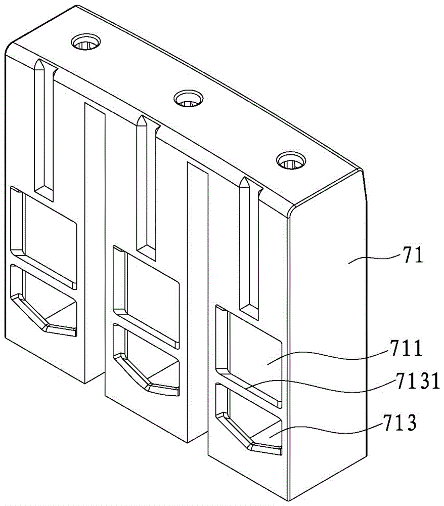
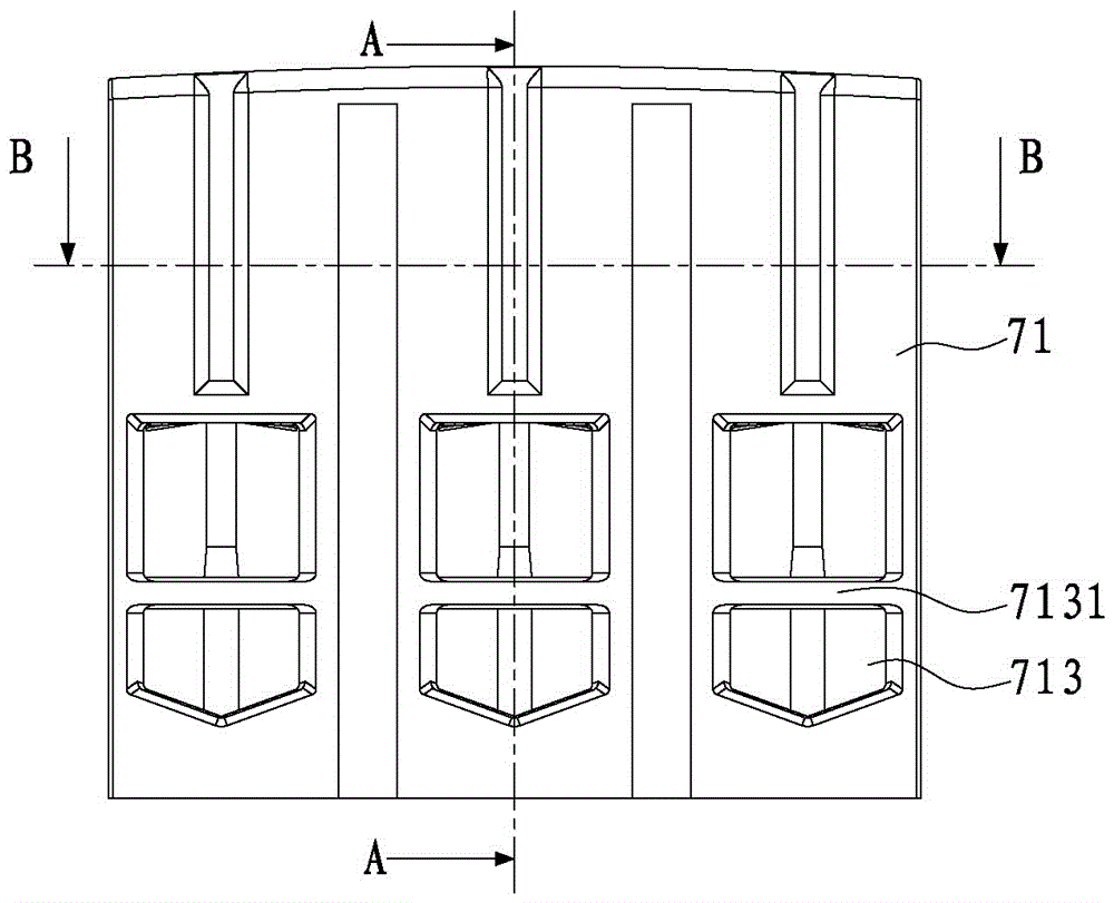
[0086] Install the terminal assembly structure 7 on the body shell 3, the terminal assembly structure 7 includes a terminal block module 71 and a terminal frame 72, the terminal block module 7...


PUM


Abstract

The invention discloses a contactor. A wiring terminal component structure is arranged on a shell. The wiring terminal component structure comprises wiring terminal modules and wiring frames, the wiring terminal modules are installed on the shell and form one or more installation cavities. One end of each installation cavity is closed, and the other end of each installation cavity is open. One side wall of each installation cavity of each wiring terminal module is provided with a passing hole, a fixed contact passes through the passing hole, the other side wall each installation cavity of each wiring terminal module is provided with a socket, and a wire is inserted in the socket. A boss is formed on each wiring frame, a through groove is formed in each wiring terminal module, each wiring frame is arranged in each installation cavity of each wiring terminal module, and the boss can move in the through groove. Clamping grooves are formed in the shell, a plug board is arranged on each wiring terminal module, the upper portion of the plug board is provided with a clamping wedge, the lower portion of the plug board slides into each clamping groove in the shell horizontally, and the fixed contact is inserted in each wiring terminal module. An arc extinguish chamber is formed in the shell, clamping grooves are also formed in the arc extinguish chamber, and the clamping wedges of the wiring terminal modules are inserted in the clamping grooves of the arc extinguish chamber. According to the contactor, wiring is convenient for the fixed contact, the installation strength of the wiring terminal module is enhanced, and the structure is simple and the cost is low.

Description

technical field [0001] The invention relates to the technical field of contactors. Background technique [0002] A contactor generally includes a body, a static contact, a contact support, a moving contact, a moving iron core, a coil bobbin, a static iron core and a base; the coil bobbin is installed in the base and inserted into the body, and the static iron is installed on the coil bobbin The core; the static contact is installed on the body, the body is installed on the base, the contact support is embedded in the body, the moving contact and the moving iron core are installed on the contact support; the arc extinguishing cover is installed on the body. When the coil on the coil bobbin is energized, the static iron core installed on the coil bobbin is excited to generate magnetic attraction to attract the moving iron core mounted on the contact support to move, driving the contact support to move, so that the moving contact and the static contact are connected. on or off...

Claims


Application Information

Patent Timeline
Patent Type & Authority Patents(China)
IPC IPC(8): H01H50/14
CPCH01H50/14
Inventor 夏昌慧田新疆
Owner XIAMEN HONGFA ELECTRICAL SAFETY & CONTROLS CO LTD
Why Eureka
Try Eureka