Optical scanner, image display device, head mount display, and head-up display
A scanner and light source technology, applied in the field of head-up displays, can solve problems such as the influence of the displacement part
- Summary
- Abstract
- Description
- Claims
- Application Information
AI Technical Summary
Problems solved by technology
Method used
Image

Examples
no. 1 approach
[0052] image display device
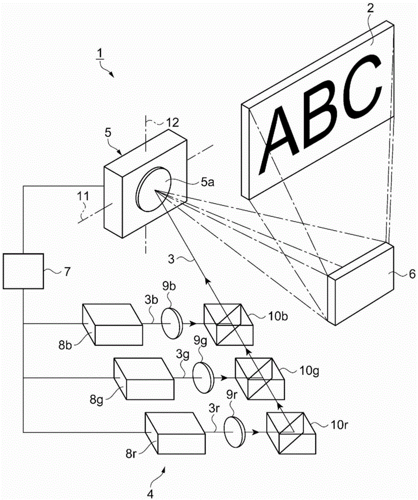
[0053] refer to figure 1 The configuration of the image display device will be described. figure 1 It is a schematic perspective view showing the configuration of the image display device. figure 1 The shown image display device 1 is a device that displays an image by two-dimensionally scanning a drawing laser 3 as light on a screen 2 such as a screen or a wall. The image display device 1 has: a drawing light source unit 4, which is used as a light source for emitting the drawing laser light 3; an optical scanner 5, which scans the drawing laser light 3; reflected by the laser beam 3; and a control unit 7 that controls the operation of the drawing light source unit 4 and the optical scanner 5. In addition, the reflecting mirror 6 may be provided as needed, and may be omitted.
[0054] The drawing light source unit 4 includes: laser light sources 8r, 8g, and 8b as light sources of red, green, and blue colors, and collimating lenses 9r, 9g, and ...
no. 2 approach
[0128] Next, use Figure 11 (a) Schematic top view showing the configuration of the optical scanner and Figure 11 (b) is a schematic side sectional view showing the structure of the optical scanner to describe one embodiment of the optical scanner. Figure 11 (b) is along Figure 11 (a) Cross-sectional view along line BB. This embodiment differs from the first embodiment in that the shape of the reflector 32 is different. In addition, descriptions of the same points as those in the first embodiment are omitted.
[0129] That is, in this embodiment, if Figure 11 As shown, the optical scanner 60 includes a structure 61 . A structure 61 is provided on the side plate 13 b of the case 13 . The structure 61 is formed by stacking the support frame portion 15 , the oxide film 15 a , and the support portion 16 on the side plate 13 b in the shape of a square tube.
[0130] The support portion 16 is provided with a first beam portion 17 and a second beam portion 22 extending in ...
no. 3 approach
[0143] Next, use Figure 12 (a) Schematic top view showing the configuration of the optical scanner and Figure 12 (b) is a schematic side cross-sectional view showing the structure of the optical scanner, describing one embodiment of the optical scanner. Figure 12 (b) is along Figure 12 (a) Cross-sectional view along CC line. This embodiment differs from the first embodiment in that hammers are provided at both ends of the displacement portion 27 . In addition, descriptions of the same points as those in the first embodiment are omitted.
[0144] That is, in this embodiment, if Figure 12 As shown, the structure 77 of the optical scanner 76 is provided with a hammer portion 78 at the end on the +Y direction side and the end on the −Y direction side in the thin plate structure portion 27 a. At the position where the hammer portion 78 is provided, the thickness of the thin plate structure portion 27 a is equal to the thickness of the plate member 33 plus the thickness of...
PUM
 Abstract
Description
Claims
Application Information
 - R&D
- Intellectual Property
- Life Sciences
- Materials
- Tech Scout
- Unparalleled Data Quality
- Higher Quality Content
- 60% Fewer Hallucinations
Browse by: Latest US Patents, China's latest patents, Technical Efficacy Thesaurus, Application Domain, Technology Topic, Popular Technical Reports.
© 2025 PatSnap. All rights reserved.Legal|Privacy policy|Modern Slavery Act Transparency Statement|Sitemap|About US| Contact US: help@patsnap.com