
Leakage non-heat-source optical fiber positioning and orientating system and monitoring method

A fiber optic positioning and orientation system technology, applied in the direction of detection of fluid at the leak point, optical exploration, measurement devices, etc., can solve the problems of affecting the monitoring results, the difficulty of peripheral current heating systems, and threats to the personal safety of operators. To achieve the effect of avoiding seepage leakage

Active Publication Date: 2015-04-29
HOHAI UNIV
View PDF5 Cites 18 Cited by
  • Summary
  • Abstract
  • Description
  • Claims
  • Application Information

AI Technical Summary

Problems solved by technology

However, the existing distributed optical fiber penetration measurement technology at home and abroad often needs to use external heat sources to heat the optical fiber to be tested. If the outer packaging layer is damaged or leakage occurs during heating, it will pose a threat to the personal safety of the operator. In addition, in the service environment of wading structures, it is often difficult to guarantee the peripheral current heating system, which greatly hinders the application and promotion of this technology in actual engineering

Method used


Image

  • Leakage non-heat-source optical fiber positioning and orientating system and monitoring method
  • Leakage non-heat-source optical fiber positioning and orientating system and monitoring method
  • Leakage non-heat-source optical fiber positioning and orientating system and monitoring method

Examples


Embodiment Construction

[0039] The present invention will be further described below in conjunction with the accompanying drawings.

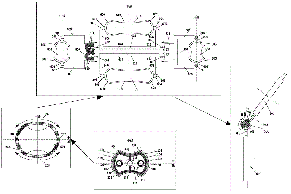
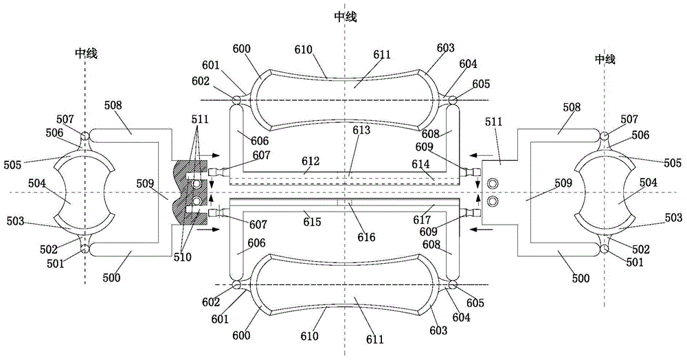
[0040] Such as Figure 1 to Figure 9 As shown, a non-heat source optical fiber positioning and orientation system for leakage of wading structures of the present invention includes several seepage monitoring devices connected by rotating brackets. Symmetrically distributed second seepage monitoring units.

[0041] The first seepage monitoring unit includes the first fiber-carrying groove 611 for fixing the monitoring fiber unit, the first fiber-carrying groove 611 is provided with a fiber-carrying sheath 610, and the two ends of the first fiber-carrying groove 611 are respectively provided with left fiber-carrying channels end 600 and the right fiber end 603, the left fiber end 600 is connected to the left ball 602 through the left handle 601, the right fiber end 603 is connected to the right ball 605 through the right handle 604, the left ball 602 is connected to the...


PUM


Abstract

The invention discloses a leakage non-heat-source optical fiber positioning and orientating system and a monitoring method. The leakage non-heat-source optical fiber positioning and orientation system comprises a plurality of leakage monitoring devices connected by rotary brackets; the leakage monitoring devices comprise first leakage monitoring units which are distributed in a fore-and-aft symmetrical manner and second leakage monitoring units which are bilaterally symmetrically distributed; leakage measurement optical fibers are distributed in the first leakage monitoring units and the second leakage monitoring units; the leakage condition of the contacted-water structural object is monitored by the leakage measurement optical fibers. The leakage non-heat-source optical fiber positioning and orientating system for the contacted-water structural object has the characteristics of no requirement for heating, distribution, omni-directional property, synchronism and the like and has the outstanding advantages on the aspects of reducing monitoring cost, promoting monitoring accuracy and engineering practicality and the like; according to the monitoring method disclosed by the invention, leakage positions and directions are obtained by flexibly arranging the leakage monitoring devices in the contacted-water structural object and comparing calibration optical fibers with the leakage measurement optical fibers; the monitoring method is simple to operate and is accurate in result.

Description

technical field [0001] The invention relates to the positioning and orientation of hidden dangers of wading structures, in particular to a non-heat source optical fiber positioning and orientation system and monitoring method for leakage of wading structures. Background technique [0002] Seepage is an important factor and prominent disease that affects the safe and long-term service of wading structures in hydraulic engineering, marine engineering, and underground engineering. Especially for earth-rock structures such as earth-rock dams and embankments, a large number of damages and even accidents are due to leakage of different degrees. According to statistics, more than 90% of embankment failures in my country, and more than one-third of the damage in earth-rock dam projects are due to leakage. Research and develop advanced and practical leakage location and orientation instruments, devices and identification methods to reliably detect the location, range, direction and si...

Claims


Application Information

Patent Timeline
IPC IPC(8): G01V8/10G01F1/7086
CPCG01D5/353G01D11/30G01F1/7086G01V8/02G01M3/04G01V8/10
Inventor 苏怀智杨孟李皓李星傅兆庆
Owner HOHAI UNIV
Learn More