Continuation imaging method suitable for cross-well seismic large-angle reflection conditions

A technology of cross-well seismic and imaging method, which is applied in seismology for logging records, etc. It can solve the problems of low imaging accuracy, difficulty in adapting to lateral changes in velocity field strength, and the influence of large-angle steep-dipping structures on imaging effects, etc.

Active Publication Date: 2015-04-29
CHINA PETROLEUM & CHEM CORP +1
View PDF4 Cites 13 Cited by
  • Summary
  • Abstract
  • Description
  • Claims
  • Application Information

AI Technical Summary

Problems solved by technology

The advantage of VSP-CDP imaging is that the algorithm is stable and easy to implement, but its disadvantages are also obvious. The main reason is that the method is based on the assumption of a horizontal layered constant velocity medium, so the imaging accuracy is low
The POSTMAP imaging of crosswell seismic is based on the VSP-CDP imaging results to further converge the diffracted waves, and the effect is better than VSP-CDP, which is equivalent to the Kirchhoff integral method, but it is difficult to adapt to the strong lateral changes of the velocity field
At the same time, since crosswell seismic reflections are mainly large-angle reflections, there are a large number of wide-angle reflections exceeding the critical angle. However, the current crosswell seismic wave equation migration method adopts the idea of ​​vertical continuation for wavefield continuation imaging, and It is not suitable for cross-well seismic reflection conditions close to wide-angle. Even if a high-precision vertical wave field continuation operator is used, the imaging effect of large-angle steep-dip structures is still affected, especially near the two wells, where the vertical continuation of the one-way wave Imaging is very difficult

Method used


Image

  • Continuation imaging method suitable for cross-well seismic large-angle reflection conditions
  • Continuation imaging method suitable for cross-well seismic large-angle reflection conditions
  • Continuation imaging method suitable for cross-well seismic large-angle reflection conditions

Examples


Embodiment 1

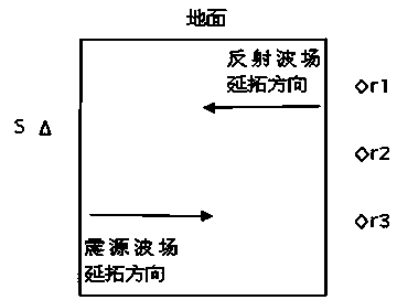
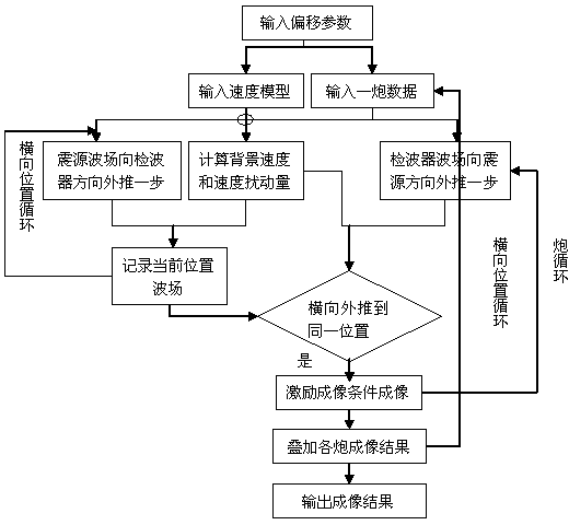
[0049] Example 1. A continuation imaging method suitable for cross-well seismic large-angle reflection conditions. According to the principle of wave equation imaging, in the case of removing the direct wave, the source wave field is extended laterally toward the geophone direction, and the geophone receiving wave field is laterally extended toward the seismic source direction Continuation, when the two wave fields are extended to the same position, imaging is performed using relevant imaging conditions, so as to realize lateral continuation imaging; the above-mentioned continuation imaging is performed on all shot points, and then multiple continuation imaging sections are superimposed. Cross-well seismic depth domain migration imaging sections can be obtained.

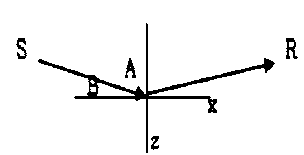
[0050] ① Principle of wave field continuation

[0051]Drawing on the mature experience of ground wave equation pre-stack depth migration imaging technology, the current one-way wave equation with high imaging accura...


PUM


Abstract

The invention discloses a continuation imaging method suitable for cross-well seismic large-angle reflection conditions. The continuation imaging method comprises the following steps: when a direct wave is removed, a wave field of a seismic source transversely extend towards a wave detector, and a receiving wave field of the wave detector transversely extends towards the seismic source; when the wave field of the seismic source and the receiving wave field of the wave detector extend to the same position, related imaging conditions are utilized for transverse continuation imaging; after images of all shot points are formed, the images are overlapped to obtain an imaging profile for cross-well seismic depth domain migration. The continuation imaging method has the advantages that a large angle of information dissemination is converted into a small angle in the direction of transverse continuation, so that the imaging effect of a vertical large-angle region is improved; separating an uplink reflected wave from a downlink reflected wave is not needed, so that the impact of the poor separating effect on an imaging result is avoided; not only the kinematic characteristics (such as temporal information) of cross-well seismic reflected wave data, but also the dynamic characteristics (such as amplitude information) of the cross-well seismic reflected wave data and the particularity of a cross-well seismic observation method are considered, so that the continuation imaging method is accurate in imaging and high in precision.

Description

technical field [0001] The invention belongs to the technical field of seismic data processing, and in particular relates to a continuation imaging method suitable for cross-well seismic large-angle reflection conditions. Background technique [0002] Due to the special observation method of crosswell seismic, the reflected wave imaging methods are generally divided into VSP-CDP imaging, travel time field continuation imaging and wave equation continuation migration imaging and other technologies. The VSP-CDP imaging method is a commonly employed method. The advantage of VSP-CDP imaging is that the algorithm is stable and easy to implement, but its disadvantages are also obvious. The main reason is that the method is based on the assumption of a horizontal layered constant velocity medium, so the imaging accuracy is low. The POSTMAP imaging of crosswell seismic is based on the VSP-CDP imaging results to further converge the diffracted waves. The effect is better than that o...

Claims


Application Information

Patent Timeline
IPC IPC(8): G01V1/40
Inventor 魏国华孟宪军王延光孔庆丰左建军魏洪泉李九生钱志武玉宏
Owner CHINA PETROLEUM & CHEM CORP
Why Eureka
Try Eureka