
Pipeline structure of air conditioner evaporator

An evaporator and pipeline technology, which is applied in the pipeline structure field of the air conditioner evaporator, can solve the problems that the air conditioner cannot be made thinner, the installation and disassembly of the air conditioner is inconvenient, etc., and achieve the effects of improving installation and maintenance efficiency, quick installation, and saving pipeline materials

Active Publication Date: 2015-04-29
AUX AIR CONDITIONING LTD BY SHARE LTD
View PDF6 Cites 9 Cited by
  • Summary
  • Abstract
  • Description
  • Claims
  • Application Information

AI Technical Summary

Problems solved by technology

[0005] In order to solve the above-mentioned defects that the traditional air conditioner cannot be made thinner and smaller, and the installation and disassembly of the air conditioner is inconvenient, the present invention provides a pipeline structure of the air conditioner evaporator that does not need to reserve a pipe routing space, the overall volume of the air conditioner becomes smaller, and is easy to install and disassemble.

Method used


Image

  • Pipeline structure of air conditioner evaporator
  • Pipeline structure of air conditioner evaporator
  • Pipeline structure of air conditioner evaporator

Examples


Embodiment Construction

[0015] In order to have a further understanding of the present invention, the following is a further description with the accompanying drawings:

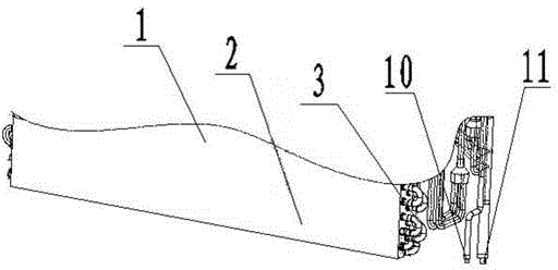
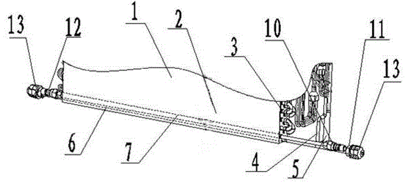
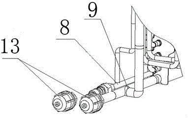
[0016] As shown in the figure, a pipe structure of an air conditioner evaporator includes an evaporator 1. The evaporator includes fins 2. The fins have curved copper pipes 3 for cooling medium to flow. The evaporator is also provided with a cooling medium The liquid inlet pipe joint 4 and the gas collecting pipe joint 4 used to flow out the gas refrigerant. The liquid inlet pipe joint 4 and the gas collecting pipe joint 5 are both set on the same side of the evaporator 1. The two joints are used to communicate with the external unit of the air conditioner to realize the refrigerant Of the loop.

[0017] At the left end of the fin 2, a left liquid inlet (not shown) and a left gas collecting port (not shown) are provided, and a right liquid inlet and a right gas collecting port (not shown) are provided at the right end of the fin. The li...


PUM


Abstract

The invention relates to the field of air conditioners, in particular to a pipeline structure of an air conditioner evaporator. The pipeline structure comprises the evaporator, wherein a liquid inlet pipe joint and an air collecting pipe joint are arranged at the same side of the evaporator, a left liquid inlet opening passage and a left air collecting opening passage are arranged at the left end of a fin, a right liquid inlet opening passage and a right air collecting opening passage are arranged at the right end of the fin, the left liquid inlet opening passage is communicated with the right liquid inlet opening passage, the left air collecting opening passage is communicated with the right air collecting opening passage, and the liquid inlet pipe joint and the air collecting pipe joint are respectively communicated with a liquid inlet pipe joint and an air collecting pipe joint at the corresponding side through a liquid inlet tee pipe and an air collecting tee pipe. The pipeline structure has the advantages that when an air conditioner is installed, a liquid inlet passage and an air collecting passage at the left end or the right end of the evaporator can be connected according to the actual requirements, the reserving of a pipe through passage at the back side of the air conditioner is not needed, the usage amount of pipeline material is saved, and the whole size and thickness of the air conditioner are improved; in addition, the air conditioner can freely realize the quick installation at the left side or the right side, and the installation and maintenance efficiency of after-sales persons is improved.

Description

Technical field [0001] The invention relates to the field of air conditioners, in particular to a pipeline structure of an air conditioner evaporator. technical background [0002] The wall-mounted air conditioner needs to connect the internal and external units through pipes during installation. The pipes on the internal unit are generally connected to the evaporator, including a liquid inlet pipe and a gas collecting pipe, and both pipes are set in the evaporator. On the same side. During installation, if the installation port is not on the same side as the liquid inlet pipe and the gas collecting pipe, the pipe needs to be connected from one side to the other. Therefore, there is often a lot of pipe running space at the lower back of the air conditioner. A long section of pipeline is inside the whole machine, which causes a waste of material cost. In addition, this kind of pipe space makes a lot of space of the air conditioning machine occupied by the tube and wasted, making ...

Claims


Application Information

Patent Timeline
Patent Type & Authority Applications(China)
IPC IPC(8): F24F13/30F25B39/02
CPCF24F13/0209F24F13/30F25B39/02
Inventor 白韡古汤汤吴庆壮黄家柏
Owner AUX AIR CONDITIONING LTD BY SHARE LTD
Learn More