Eureka AIR delivers breakthrough ideas for toughest innovation challenges, trusted by R&D personnel around the world.
Straw direct combustion heating device
What is Al technical title?
Al technical title is built by PatSnap Al team. It summarizes the technical point description of the patent document.
A heating device and straw technology, applied in the direction of combustion control, combustion equipment, solid fuel combustion, etc., can solve the problems of complex operation, low thermal efficiency, energy waste, etc., achieve simple operation, uninterrupted heating, and reduce heating costs Effect
Inactive Publication Date: 2017-11-03
CHANGCHUN UNIV OF TECH
View PDF8 Cites 0 Cited by
Summary
Abstract
Description
Claims
Application Information
AI Technical Summary
This helps you quickly interpret patents by identifying the three key elements:
Problems solved by technology
Method used
Benefits of technology
Problems solved by technology
[0002] Due to the seasonality and inconvenient transportation of straw, a large amount of straw is burned in the spring, causing environmental pollution and energy waste; burning straw for heating is one of the ways to effectively use straw, but the current straw burning heating equipment Either through manual filling (straw or straw particles), which is time-consuming and laborious; or through gasification, which has complicated operation and low thermal efficiency, so it has not been widely used
Method used
Image
Click on the blue label to locate the original text in one second.
Reading with bidirectional positioning of images and text.
Examples
Embodiment Construction
[0009] Below in conjunction with accompanying drawing, technical scheme of the present invention is described in further detail:
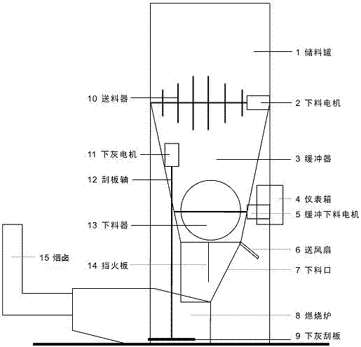
[0010] Such as figure 1 As shown, the present invention consists of a storage tank 1, a feeding motor 2, a buffer tank 3, an instrument box 4, a buffer feeding motor 5, a fan 6, a feeding port 7, a combustion furnace 8, an ash scraper 9, a feeding Device 10, lower ash motor 11, scraper shaft 12, feeder 13, fire baffle 14, chimney 15 are formed.
[0011] The feeder (13) is made into a circular hollow structure with a width of 1CM iron bars, and the circular surface is evenly distributed with thorns about 5CM long, so as to reach the purpose of quantitative stalks.
[0012] An automatic feeder 10 is set between the storage tank 1 and the buffer tank 2, an automatic feeder 13 is set between the buffer tank 3 and the feeding port 7, an automatic dust scraper is set in the combustion furnace 8, and an automatic ash scraper is set at the feeding port 7....
PUM
Abstract
The invention discloses a straw direct combustion heating device, which comprises a storage tank, a feeding motor, a buffer tank, an instrument box, a feeding motor, a blowing fan, a feeding port, a fuel furnace, an ash lowering scraper, a feeder, a lower Ash motor, scraper shaft, feeder, fire baffle, chimney. An automatic feeder is set between the storage tank and the buffer tank, an automatic feeder is set between the buffer tank and the discharge port, an automatic ash discharge scraper is provided in the combustion furnace, and an automatic fan and a fire baffle are provided at the discharge port. Put the simply cut straw into the storage tank and the buffer tank; then select the firepower from the control panel of the controller or manually set the parameters; then ignite the straw in the combustion furnace, start the straw burning controller, and the controller will Firepower parameters, automatic feeding, ash and air supply, make the straw in the furnace burn with high efficiency and achieve the purpose of uninterrupted heating. The invention is convenient and simple to use, and will greatly reduce the heating costs of rural families and greenhouses in winter.
Description
technical field [0001] The invention relates to a heat supply device for direct combustion of straw, in particular to a heat supply device capable of automatically cutting materials (straw), automatically removing ash, and capable of burning straw with high efficiency. Background technique [0002] Due to the seasonality and inconvenient transportation of straw, a large amount of straw is burned in the spring, causing environmental pollution and energy waste; burning straw for heating is one of the ways to effectively use straw, but the current straw burning heating equipment Either through manual filling (straw or straw particles), which is time-consuming and laborious; or through gasification, which has complicated operation and low thermal efficiency, so it has not been widely used. [0003] This device adopts mechanical design, intelligent control and sensor technology to provide a simple structure and automatic straw direct combustion heating equipment, which can effect...
Claims
Application Information
Patent Timeline
Application Date:The date an application was filed.
Publication Date:The date a patent or application was officially published.
First Publication Date:The earliest publication date of a patent with the same application number.
Issue Date:Publication date of the patent grant document.
PCT Entry Date:The Entry date of PCT National Phase.
Estimated Expiry Date:The statutory expiry date of a patent right according to the Patent Law, and it is the longest term of protection that the patent right can achieve without the termination of the patent right due to other reasons(Term extension factor has been taken into account ).
Invalid Date:Actual expiry date is based on effective date or publication date of legal transaction data of invalid patent.