
Water-lubricated high-pressure plunger pump and hand-held high-pressure injection device

A high-pressure plunger pump and water inlet technology, applied in the hydraulic field, can solve the problems of difficult water flow channel design, inconvenient product portability, difficult design of water flow channel, etc., achieve good water flow channel design, good cooling, and increase design space Effect

Active Publication Date: 2017-10-20
WOER TECH
View PDF5 Cites 0 Cited by
  • Summary
  • Abstract
  • Description
  • Claims
  • Application Information

AI Technical Summary

Problems solved by technology

[0003] In the process of realizing and using the existing high-pressure plunger pump, the inventor found that there are at least the following problems in the prior art: since the water inlet and the water outlet are designed on the same end cover, it is difficult to design the water flow channel, especially When the high-pressure plunger pump needs to be miniaturized, the design of the water flow channel is more difficult; in addition, if the miniaturized high-pressure plunger pump is applied to a hand-held high-pressure injection device, such as a hand-held high-pressure fire extinguishing equipment, a hand-held high-pressure For flushing equipment, etc., since the water outlet of the hand-held high-pressure spray device needs to be designed at the front end, and at this time, the water inlet is also designed at the front end, which will inevitably make the product inconvenient to carry and install

Method used


Image

  • Water-lubricated high-pressure plunger pump and hand-held high-pressure injection device
  • Water-lubricated high-pressure plunger pump and hand-held high-pressure injection device
  • Water-lubricated high-pressure plunger pump and hand-held high-pressure injection device

Examples


Embodiment 1

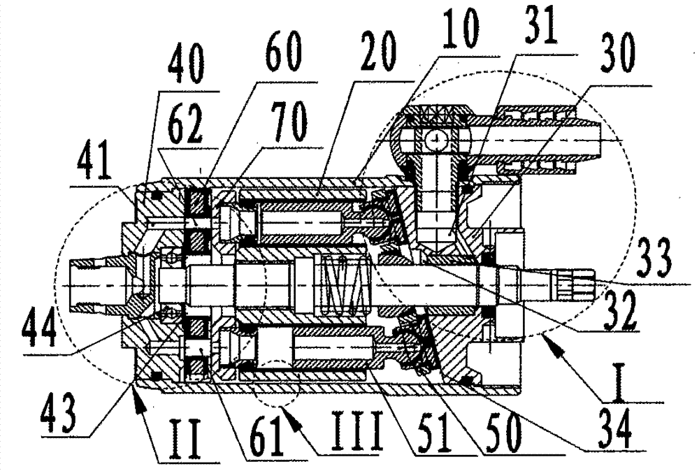
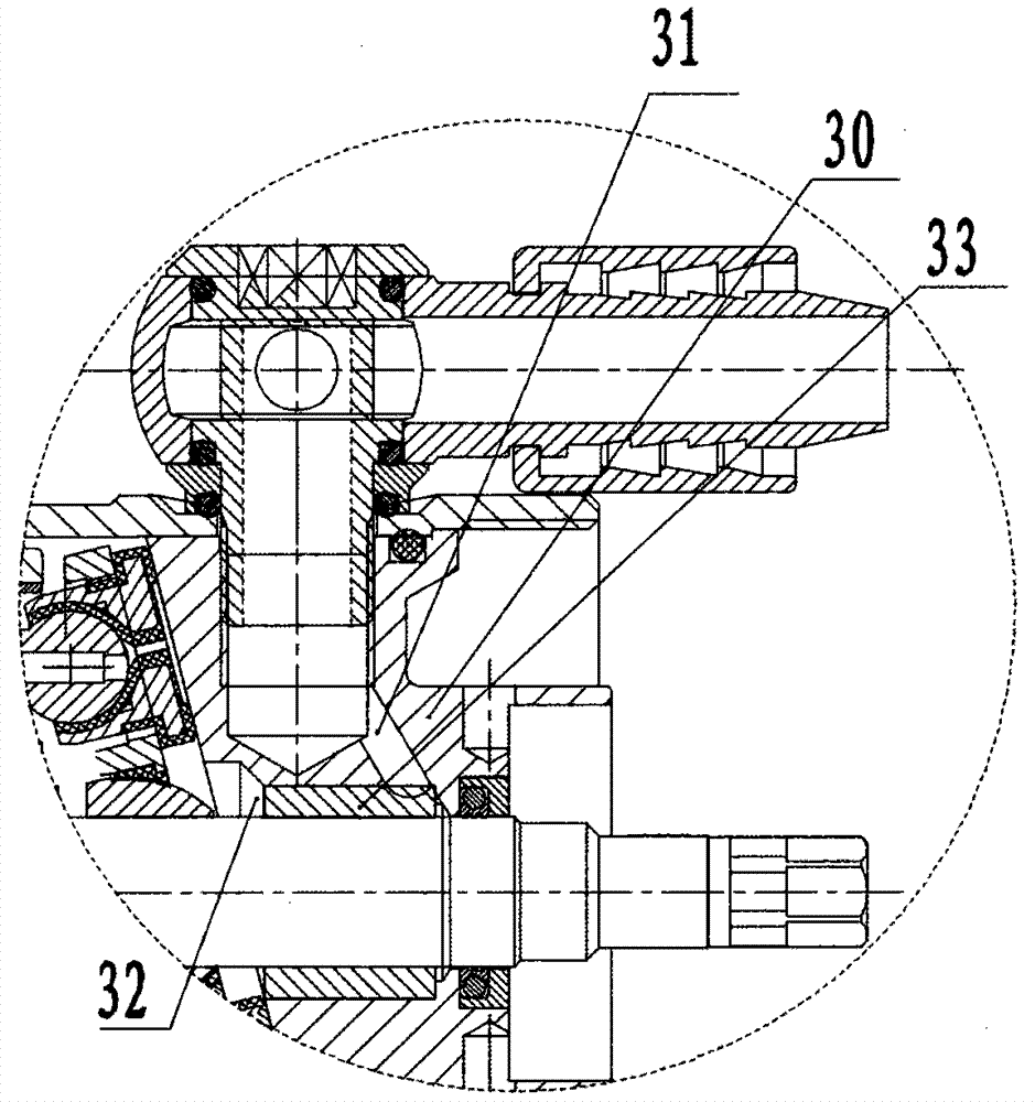
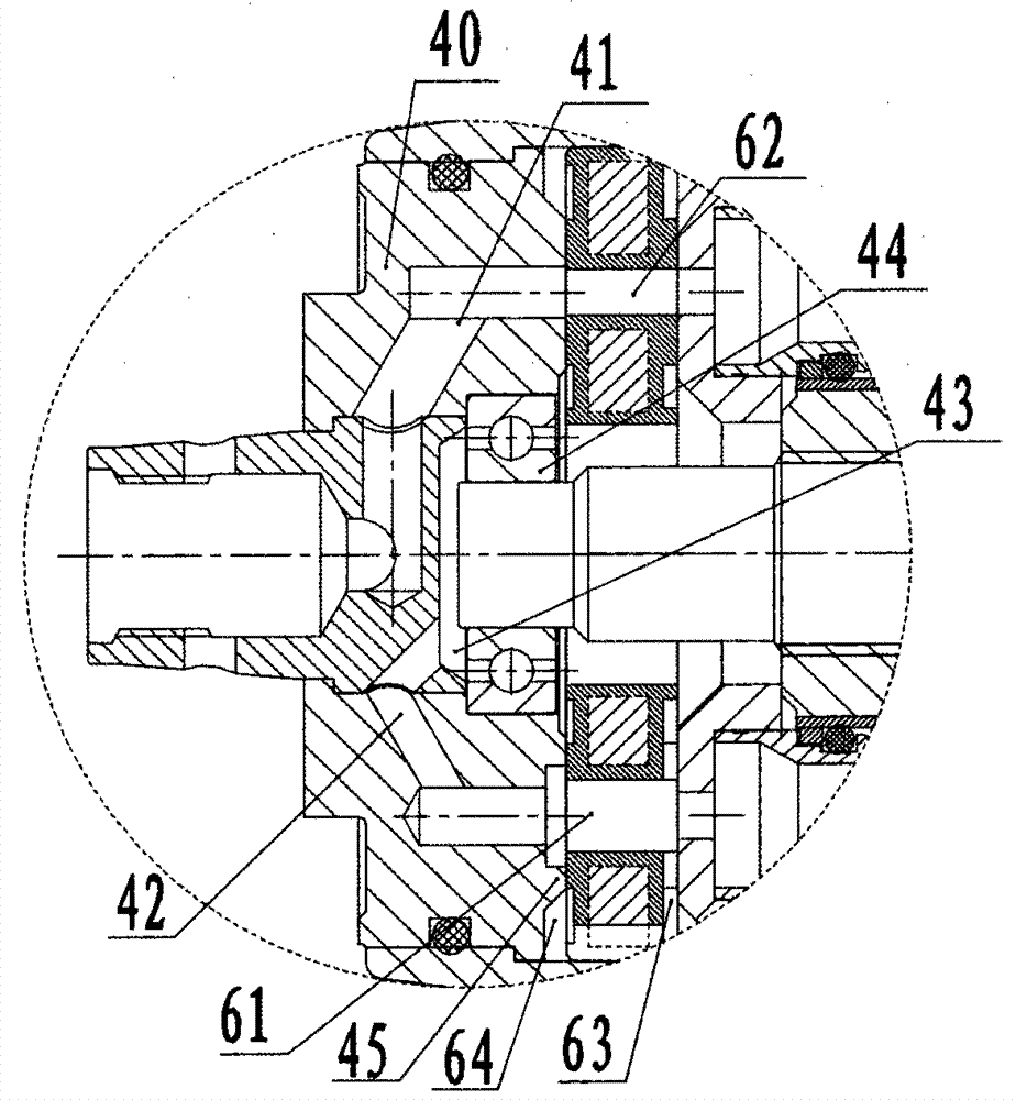
[0033] Embodiments of the present invention provide a water-lubricated high-pressure plunger pump, such as figure 1 As shown, the high-pressure plunger pump includes a housing 10 with a through hole, and a cylinder body 20 is arranged in the through hole, and cylinder holes 21 are arranged on the cylinder body according to a circular array; in order to facilitate the design of the flow channel, the present invention In the embodiment, the two end caps are respectively designed as the water inlet end cap 30 and the water outlet end cap 40, specifically as figure 1 As shown, one end of the through hole is provided with a water inlet cover 30, that is figure 1 The right end of the middle through hole is provided with a water inlet end cover 30, and a return plate 50 is arranged between the cylinder body 20 and the water inlet end cover 30. The return plate is provided with a plunger shoe assembly 51 inserted into the cylinder hole, through which the plunger slides. The piston mo...

Embodiment 2

[0047] The embodiment of the present invention also provides a high-pressure plunger pump, specifically a water-lubricated high-pressure plunger pump for lubricating bearings, such as figure 1 As shown, it includes a housing 10 with a through hole, a cylinder body 20 is arranged in the through hole, cylinder holes 21 are arranged on the cylinder body 20 according to a circular array, and water inlet end caps 30 are respectively provided at both ends of the through hole. and the water outlet cover 40, a distribution plate 60 is provided between the cylinder body 20 and the water outlet cover 40, the water inlet cover 30 is provided with a water inlet channel 31 that can communicate with the outside, and the water outlet cover 40 is provided with a The water outlet channel 41 communicates with the outside, and the water inlet channel 31 communicates with the water inlet hole 61 of the distribution plate through the side gap 22 between the cylinder body and the casing. In order t...

Embodiment 3

[0056] An embodiment of the present invention provides a high-pressure plunger pump, specifically a water-lubricated high-pressure plunger pump with lubricated bearings, such as figure 1 As shown, the high-pressure plunger pump includes a housing 10 with a through hole, and a cylinder body 20 is arranged in the through hole, and cylinder holes 21 are arranged on the cylinder body 20 according to a circular array, and the two ends of the through hole are respectively provided with The water inlet end cover 30 and the water outlet end cover 40, a return plate 50 is arranged between the cylinder body 20 and the water inlet end cover 30, and a plunger shoe assembly 51 inserted into the cylinder hole is provided on the return plate 50; the water inlet The end cover 30 is provided with a water inlet channel 31 that can be communicated with the outside. In the present invention, the water inlet channel 31 is provided on the end cover with a return plate, so that the water flow channel...


PUM


Abstract

An embodiment of the invention discloses a water-lubrication high-pressure plunger pump and a handheld high-pressure jet apparatus, and relates to the technical field of hydraulic pressures. By the aid of the water-lubrication high-pressure plunger pump and the handheld high-pressure jet apparatus, the problem of inconvenience in designing water flow channels in the prior art can be solved. The water-lubrication high-pressure plunger pump comprises a shell with a through hole. Cylinders are arranged in the through hole, and cylinder holes are circumferentially formed in the cylinders; a water inlet end cover is arranged at one end of the through hole, a water outlet end cover is arranged at the other end of the through hole, a water inlet channel which can be communicated with the external is arranged on the water inlet end cover, a water outlet channel which can be communicated with the external is arranged on the water outlet end cover and is communicated with a water outlet hole in a flow distribution disc, and the water inlet channel is communicated with a water inlet hole in the flow distribution disc via side gaps between the cylinders and the shell. The water-lubrication high-pressure plunger pump and the handheld high-pressure jet apparatus in the embodiment of the invention are mainly applied to miniaturized hydraulic equipment, and the water-lubrication high-pressure plunger pump is particularly applied to the handheld high-pressure jet apparatus.

Description

technical field [0001] The invention relates to the field of hydraulic technology, in particular to a water-lubricated high-pressure plunger pump and a hand-held high-pressure injection device. Background technique [0002] The high-pressure plunger pump performs reciprocating piston movement in the cylinder bore of the cylinder body through its plunger to realize the suction and booster pumping of the liquid, and the cylinder body of the high-pressure plunger pump is generally installed inside the casing, which mainly includes the casing and end caps at both ends of the housing. The water inlet and the water outlet of the existing high-pressure plunger pump are generally all arranged at the same end cover, so the water inlet and the water outlet can directly correspond to the cylinder bore of the cylinder body. [0003] In the process of realizing and using the existing high-pressure plunger pump, the inventor found that there are at least the following problems in the pri...

Claims


Application Information

Patent Timeline
Patent Type & Authority Patents(China)
IPC IPC(8): F04B1/04F04B53/16B05B9/04
Inventor 蒋祖光
Owner WOER TECH
Learn More