
Sensor filling machine

A filling machine and sensor technology, applied in the field of sensor filling machines, can solve the problems of adjusting the filling angle at the filling outlet to increase the internal pressure, insufficient filling force, sensor filling, etc., so as to improve convenience and prevent solution The effect of spraying and preventing the splash of the solution

Pending Publication Date: 2022-04-05
CHANGZHOU AITE TECH
View PDF11 Cites 0 Cited by
  • Summary
  • Abstract
  • Description
  • Claims
  • Application Information

AI Technical Summary

Problems solved by technology

[0004] When filling, it is difficult to adjust the filling angle at the filling outlet while increasing the internal pressure, which may easily cause the filling to be separated, and it is difficult to better fill the sensor into the device due to insufficient filling force.

Method used


Image

  • Sensor filling machine
  • Sensor filling machine
  • Sensor filling machine

Examples


Embodiment Construction

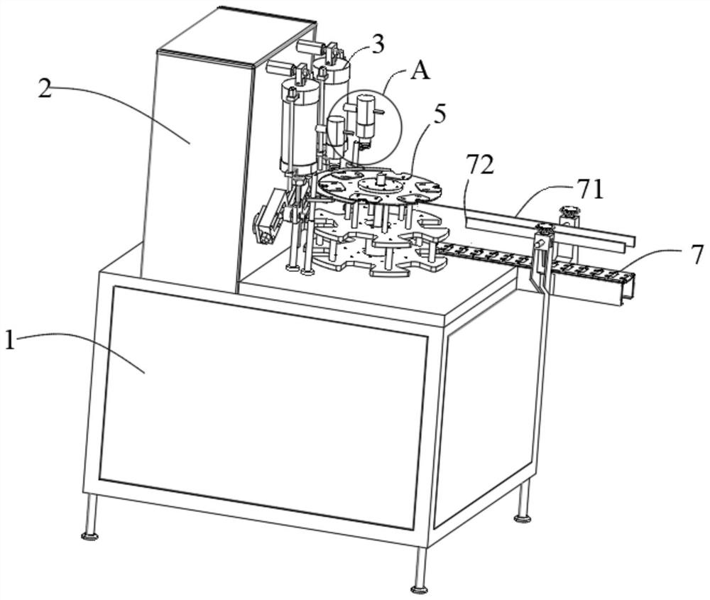
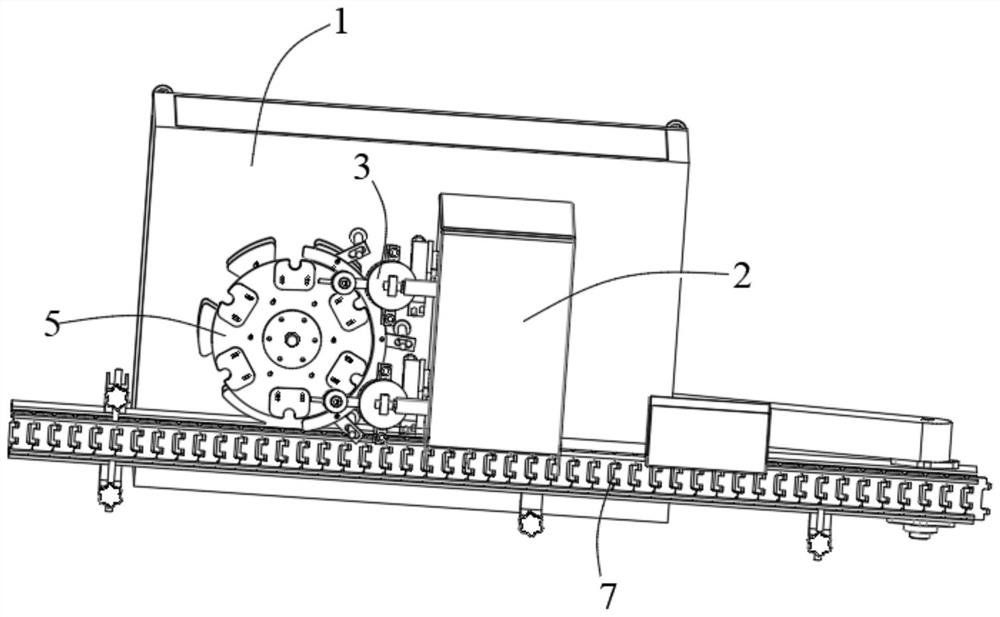
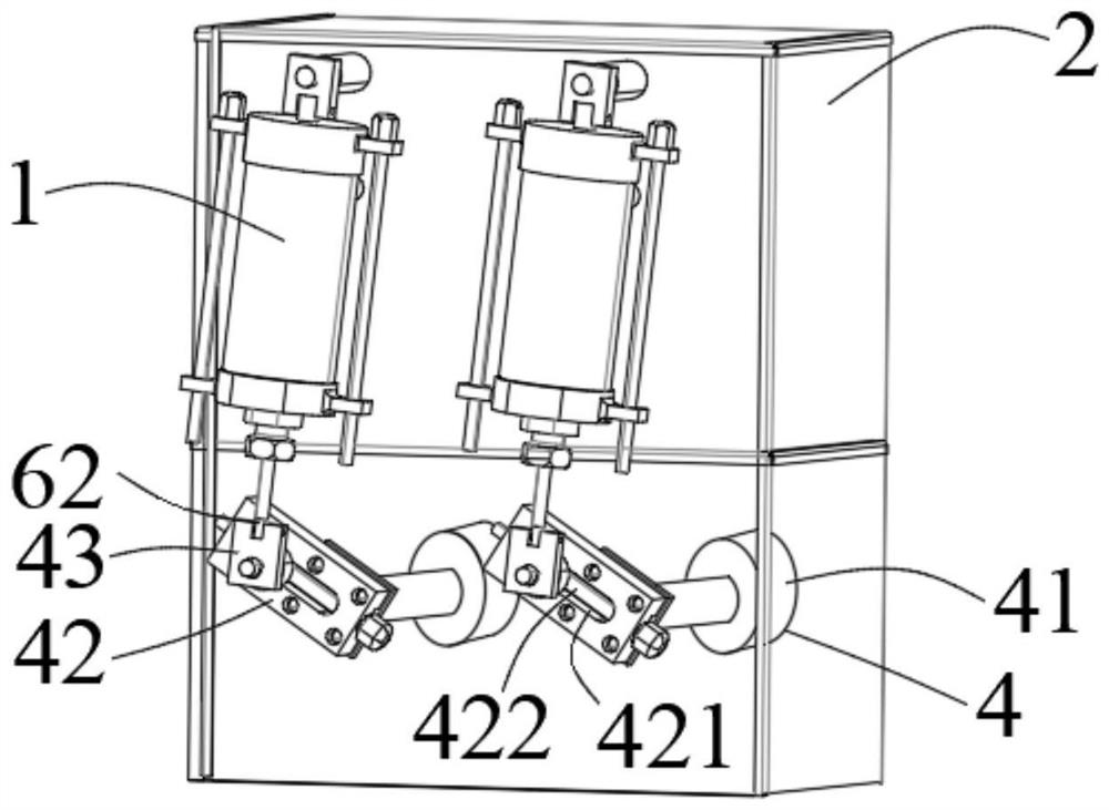
[0030] The present invention is described in further detail now in conjunction with accompanying drawing. These drawings are all simplified schematic diagrams, which only illustrate the basic structure of the present invention in a schematic manner, so they only show the configurations related to the present invention.

[0031] like Figure 1-5 As shown, a sensor filling machine of the present invention includes a workbench 1 and a filling box 2 fixed on one side of the top of the workbench 1, and the filling equipment also includes a filling box installed on one side of the filling box 2 Two groups of storage tanks 3 and the driving part 4 installed at the bottom of the storage tank 3, and the rotating part 5 installed at the top of the workbench 1; one side of the storage tank 3 is hinged with a spray tank 31; There is a pressurizing part 6 inside the tank 3, and the driving part 4 drives the pressurizing part 6 up and down; the pressurizing part 6 includes a pressurizing p...


PUM


Abstract

The invention relates to a sensor filling machine which comprises a workbench and a filling box fixed to one side of the top of the workbench, and further comprises two sets of storage tanks installed on one side of the filling box, driving parts installed at the bottoms of the storage tanks and a rotating part installed at the top of the workbench. The pressurizing plate is arranged in the storage tank, and when the driving part drives the storage tank to swing left and right, the pressurizing plate extrudes a solution in the storage tank to be sprayed out of the spraying tank. A through hole groove and a sliding rod are formed in a rotating plate, a sliding block can be connected to the sliding rod in a sliding mode and can slide in the through hole groove, then a first motor is used for driving the rotating plate to rotate, a pressurizing plate is stretched back and forth while rotating, the pressurizing plate stretches back and forth to extrude a solution, and the pressurizing effect is achieved; and the sliding block slides on the sliding rod to drive the storage tank to swing left and right, and angle adjustment of the position of the nozzle is achieved.

Description

technical field [0001] The invention relates to the field of filling, in particular to a sensor filling machine. Background technique [0002] In Chinese patent application 201710475648.8, a sensor chip assembly equipment is disclosed, which includes a sensor chip assembly frame, a sensor chip loading device, a sensor chip grabbing device, a height measuring device, and a film tearing device; the sensor chip loading device is set on The sensor chip assembly frame; the sensor chip grabbing device is set on the sensor chip assembly frame, and is located on one side of the sensor chip feeding device, and the sensor chip grabbing device corresponds to the sensor chip feeding device; the height measuring device is set on the sensor chip assembly The frame, the film tearing device is arranged on the sensor chip assembly frame, the film tearing device is located on one side of the height measuring device, and the film tearing device corresponds to the sensor chip grabbing device. ...

Claims


Application Information

Patent Timeline
Patent Type & Authority Applications(China)
IPC IPC(8): B67C3/26B67C3/24
Inventor 王茂祥
Owner CHANGZHOU AITE TECH
Learn More