
Pneumatic muscle and its control system

A pneumatic muscle, inflation and deflation technology, applied in the field of pneumatic muscle and its control system, can solve the problems of complicated system and difficult to apply portable execution equipment, etc., achieve the effect of reducing high-pressure air source and improving portability

Inactive Publication Date: 2018-05-04
CHINA JILIANG UNIV
View PDF7 Cites 0 Cited by
  • Summary
  • Abstract
  • Description
  • Claims
  • Application Information

AI Technical Summary

Problems solved by technology

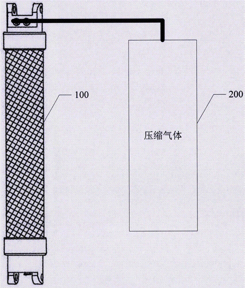
In the prior art, please refer to figure 1 , is a schematic diagram of the existing pneumatic muscle drive system, the pneumatic muscle 100 needs an independent external air source device 200 such as an air compressor to provide compressed gas, and needs to use air control devices such as solenoid valves to realize the inflation and deflation functions of the pneumatic muscle, so that The system is cumbersome and difficult to apply to portable execution equipment

Method used


Image

  • Pneumatic muscle and its control system
  • Pneumatic muscle and its control system
  • Pneumatic muscle and its control system

Examples


Embodiment Construction

[0026] The technical solutions of the present invention will be clearly and completely described below in conjunction with the accompanying drawings. Apparently, the described embodiments are some of the embodiments of the present invention, but not all of them. Based on the embodiments of the present invention, all other embodiments obtained by persons of ordinary skill in the art without making creative efforts belong to the protection scope of the present invention.

[0027] In the description of the present invention, it should be noted that the terms "center", "upper", "lower", "left", "right", "vertical", "horizontal", "inner", "outer" etc. The indicated orientation or positional relationship is based on the orientation or positional relationship shown in the drawings, and is only for the convenience of describing the present invention and simplifying the description, rather than indicating or implying that the referred device or element must have a specific orientation, ...


PUM


Abstract

The invention discloses a pneumatic muscle and a control system thereof. The pneumatic muscle comprises a pneumatic muscle body, a first sealing element, a second sealing element, a charging and discharging device arranged at the end, close to the first sealing element, wherein the pneumatic muscle body is provided with an axial hollow cavity and is used for charging / discharging a compressed gas to provide tension along the axial direction of the pneumatic muscle body; the first sealing element and the second sealing element are arranged at two axial ends of the pneumatic muscle body to seal the hollow cavity of the pneumatic muscle body; the first sealing element is provided with a charging / charging hole communicating with the hollow cavity of the pneumatic muscle body; the charging and discharging device is used for charging the gas outside the pneumatic muscle body into the hollow cavity of the pneumatic muscle body through the charging / discharging hole in a pressurized manner after receiving the pressurized trigger signal; and the charging and discharging device discharges the high-pressure gas in the pneumatic muscle body out of the pneumatic muscle body through the charging / discharging hole after receiving the decompressed trigger signal. The high-pressure gas is provided to the pneumatic muscle through air pressure surrounding the pneumatic muscle, so that an extra high-pressure gas source can be reduced and the application portability of the pneumatic muscle is improved.

Description

technical field [0001] The invention relates to the field of drivers, in particular to a pneumatic muscle and its control system. Background technique [0002] Pneumatic muscle is a new type of actuator that can imitate the contraction of biological muscles. Due to its advantages of high flexibility, light weight, convenient use, fast response, and low cost, it is widely used in various bionic machinery and other driving fields. The pneumatic muscle is mainly composed of three parts: an inflatable elastic hose, a braided mesh that restrains the deformation of the elastic hose, and a clamp. The outside is a layer of high-strength fiber braided mesh. When it is filled with compressed air, the pneumatic muscle structure contracts in the axial direction and expands in the radial direction. If one end of it is fixed, the other end is connected to a load to generate drive through axial contraction. force. [0003] Pneumatic muscles have excellent performance and have good potent...

Claims


Application Information

Patent Timeline
Patent Type & Authority Patents(China)
IPC IPC(8): F15B15/10F15B15/20F15B3/00F15B21/08
CPCF15B3/00F15B15/103F15B15/202F15B21/08F15B2215/30
Inventor 王斌锐张云郭振武张斌金英连金海龙
Owner CHINA JILIANG UNIV
Learn More