
A spinning coiler

A winding machine and spinning technology, which is used in textiles and papermaking, conveying filamentous materials, and bundling of newly ejected filaments, etc. The effect of falling off and shortening the hanging time

Active Publication Date: 2015-04-29
TMT MACHINERY INC
View PDF13 Cites 18 Cited by
  • Summary
  • Abstract
  • Description
  • Claims
  • Application Information

AI Technical Summary

Problems solved by technology

Therefore, it takes time to hang the thread, and accordingly, the amount of thread to be discarded increases.
In addition, in the case of a failure of threading toward a part of the distribution guide, it is impossible to perform threading again only on such a distribution guide. from) re-hanging

Method used


Image

  • A spinning coiler
  • A spinning coiler
  • A spinning coiler

Examples


Embodiment Construction

[0040] Hereinafter, embodiments of the present invention will be described with reference to the drawings.

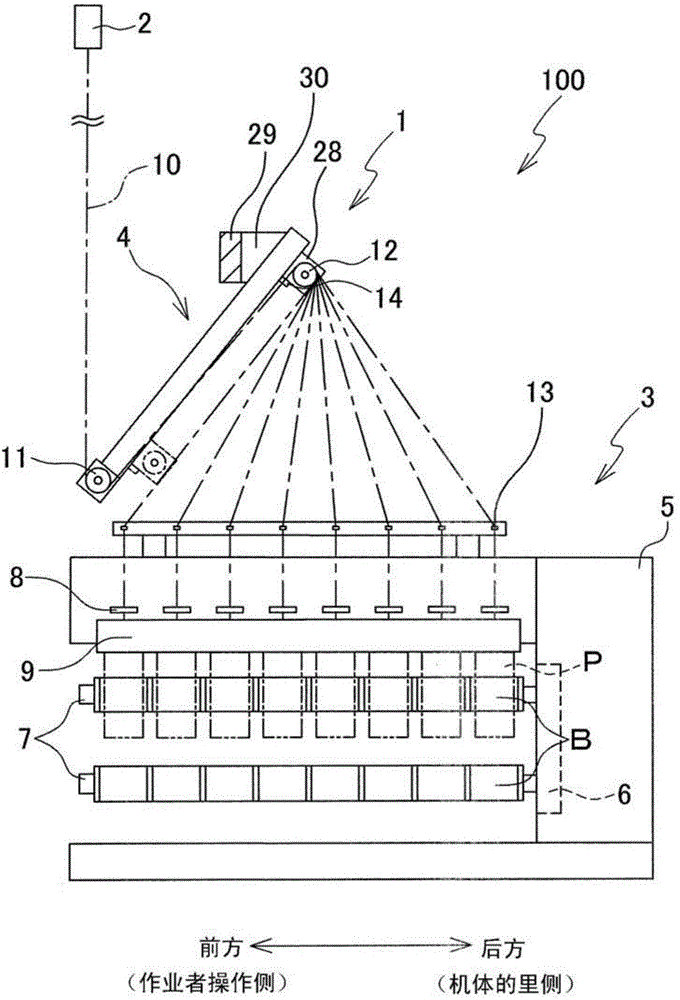
[0041] Such as figure 1 As shown, the spinning winder 100 has: a spinning drawing part 1 that draws a plurality of yarns 10 spun from a spinning machine 2; The winding part 3 of a bobbin B. In the following description, the front end side of the bobbin holder 7 described later is defined as the side on which the operator operates the spinning winder 100, that is, the front, and the opposite side is defined as the rear.

[0042] (Spinning Draw Department)

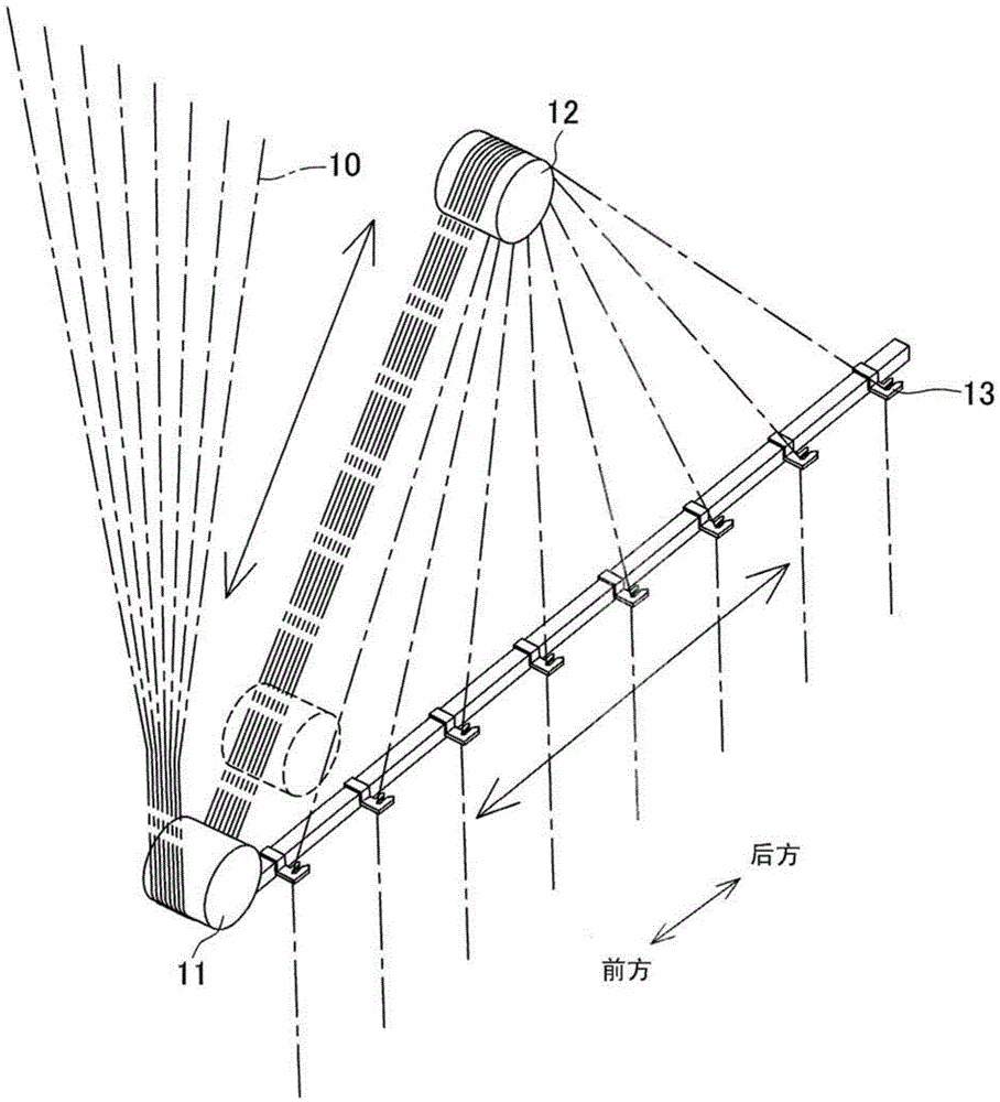
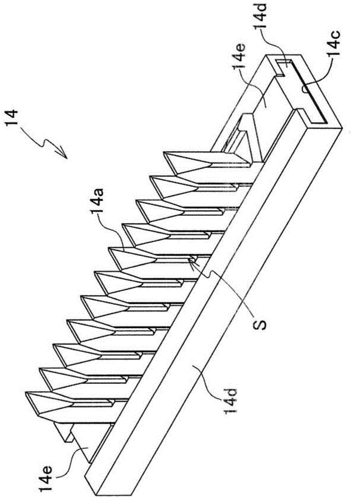
[0043] First, the spinning drawing unit 1 will be described. Such as figure 1 , figure 2 As shown, the spinning drawing unit 1 has a first godet roll 11 , a second godet roll 12 , a yarn regulating guide 14 , and a roll lifting mechanism 4 . A plurality of yarns 10 spun out from the spinning machine 2 are drawn by the first godet roll 11 and the second godet roll 12, and are drawn toward the coiling portion arr...


PUM


Abstract

A spinning coiler is provided and capable of shortening silk hanging time and allowing silk to be easily hung again. The spinning coiler winds a plurality of silk threads spun from a spinning machine around a plurality of bobbins mounted on a bobbin support. A silk guide roller mounted to the spinning coiler can move between a production position when the plurality of silk threads are wound around the bobbins and a silk hanging position which is closer to one end of the bobbin support than the production position. A plurality of transverse-movement fulcrum guide elements can move among a production position when the plurality of silk threads conveyed from the silk guide roller are guided to the plurality of bobbins, a silk hanging position which is closer to the bobbin support than the production position, and a silk hanging position where transverse-movement fulcrum guide elements are centralized in a manner that gaps are reduced than that of the production position.

Description

technical field [0001] The present invention relates to a spinning winder for winding a plurality of yarns spun from a spinning machine on a plurality of bobbins mounted on a bobbin holder. Background technique [0002] As a conventional spin winder, for example, there is a spin winder described in Patent Document 1. This spinning winder includes a first godet, a second godet, a winding device, and the like. The multiple yarns spun continuously from the spinning machine are pulled by the first godet roll and the second godet roll, conveyed to the winding device below, and wound up on multiple bobbins assembled on the bobbin holder respectively. In addition, the winding device has a plurality of distribution guides arranged at intervals in the axial direction of the bobbin holder. The plurality of yarns fed from the second godet are separated by the plurality of distributing guides, then fed toward the plurality of bobbins and wound on the plurality of bobbins, respectively...

Claims


Application Information

Patent Timeline
IPC IPC(8): D01D7/00
CPCB65H57/16D01D7/00B65H2701/31B65H57/003
Inventor 桥本欣三加贺田翔菊池纯
Owner TMT MACHINERY INC
Learn More