
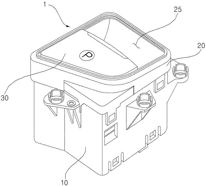
Automobile parking brake switch assembly

A parking brake and switch assembly technology, which is applied in the field of parking brake switch assembly structure, can solve problems such as rigid wear, difficult installation of the joystick, and inability to maintain rigidity continuously, so as to improve rigid wear resistance and improve assembly The effect of simplicity

Inactive Publication Date: 2017-07-21
SUZHOU RUIYAN ELECTRONICS TECH CO LTD +1
View PDF5 Cites 0 Cited by
  • Summary
  • Abstract
  • Description
  • Claims
  • Application Information

AI Technical Summary

Problems solved by technology

[0011] In view of the above-mentioned defects in the prior art, the purpose of the present invention is to propose a car parking brake switch assembly, which solves the problem that the traditional car parking brake switch is prone to rigid wear when the driver exerts too much force, and cannot continue to maintain its rigidity. Difficulty installing the joystick

Method used


Image

  • Automobile parking brake switch assembly
  • Automobile parking brake switch assembly
  • Automobile parking brake switch assembly

Examples


Embodiment Construction

[0024] The specific implementation manners of the present invention will be described in further detail below in conjunction with the accompanying drawings of preferred embodiments, so that the advantages and features of the technical solution of the present invention can be more easily understood and grasped. However, the present invention is not limited to the embodiments shown below, but can be embodied in various forms. This implementation example is only to show the present invention more completely, so that those with ordinary knowledge in the technical field of the present invention can fully understand the scope of the present invention, and it is defined according to the scope of the application of the present invention. The reference signs mentioned throughout the detailed description refer to the same constituent element.

[0025] Figure 5 In order to show the composition of the automobile parking brake switch assembly of the present invention, the bottom view of ...


PUM


Abstract

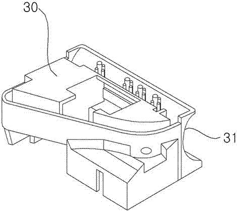
The invention discloses a vehicle parking brake switch assembly. The vehicle parking brake switch assembly comprises a mounting body part, a facing body part and an operation rod, wherein the mounting body part is inserted into a vehicle center control seat and is internally provided with a printed circuit board of a vehicle master controller; the facing body part is mounted on the upper end of the mounting body part in a joint manner and is provided with an operation groove part; fingers of an operator can be inserted into the operation groove part; the facing body part is provided with a hinge protruding part; the operation rod is provided with a hinge inserting opening which serves as a rotation center; the operation rod is rotationally installed in the operation groove part of the facing body part; a specific curvature radiused circular part is arranged between the base surface for starting protruding and the peripheral surface of the hinge protruding part on the hinge protruding part. Through the adoption of the design of the circular part of the switch assembly, the resistance to rigid abrasion of the hinge protruding part is improved; the switch assembly is effectively suitable for driver habits with different switch operation forces; meanwhile, the simplicity and convenience in assembly of the operation rod are improved.

Description

technical field [0001] The invention relates to an automobile parking brake switch assembly, in particular to a parking brake switch assembly structure which improves the strength of the joystick in the manipulation direction and makes the joystick easier to assemble. Background technique [0002] In general, the car is equipped with a parking brake system that prevents the car from moving freely and parks it firmly on the ground when parking, and the parking brake system is installed through the parking brake switch installed inside the car. Assembly controls. [0003] figure 1 It is an oblique view showing an implementation example of an automobile parking brake switch assembly using the prior art; figure 2 and image 3 for display figure 1 The squint d of the joystick that changes the direction of observation in the composition; Figure 4 for display figure 1 The plan view of the main body of the veneer in the composition of . [0004] Adopt the implementation exa...

Claims


Application Information

Patent Timeline
Patent Type & Authority Patents(China)
IPC IPC(8): B60T7/10
CPCB60T7/10
Inventor 朱成泰
Owner SUZHOU RUIYAN ELECTRONICS TECH CO LTD
Learn More