
Multi-station clamping device

A clamping device, multi-station technology, applied in the direction of clamps, manufacturing tools, etc., can solve the problem of not being able to clamp different sizes and shapes at the same time

Inactive Publication Date: 2015-04-29
CHONGQING YIZHU MACHINERY MFG
View PDF0 Cites 3 Cited by
  • Summary
  • Abstract
  • Description
  • Claims
  • Application Information

AI Technical Summary

Problems solved by technology

[0005] The invention provides a multi-station clamping device to solve the problem that the existing multi-station clamping device cannot clamp workpieces with different sizes and shapes at the same time

Method used


Image

  • Multi-station clamping device

Examples


Embodiment Construction

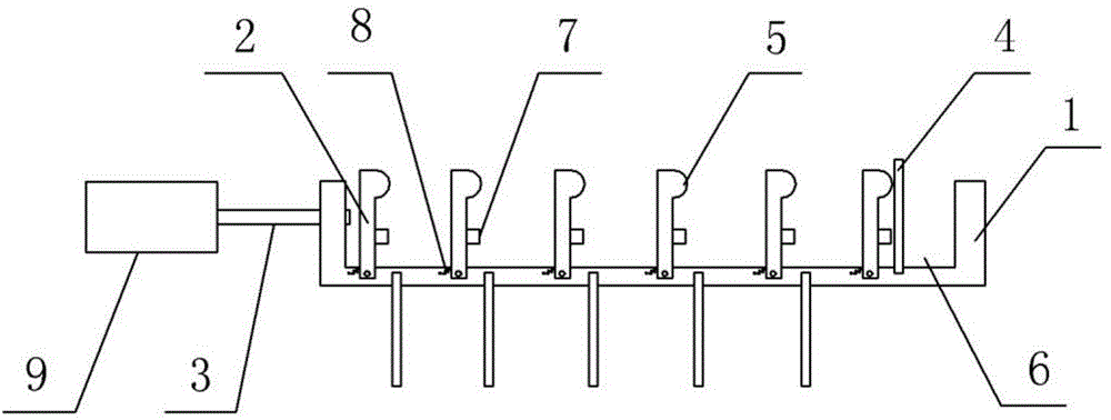
[0015] The reference signs in the accompanying drawings of the description include: base 1 , jaw 2 , control rod 3 , positioning plate 4 , cam segment 5 , groove 6 , baffle plate 7 , tension spring 8 , and hydraulic rod 9 .

[0016] Such as figure 1 As shown, a multi-station clamping device in this embodiment includes a base 1 , several jaws 2 arranged on the base 1 , a positioning plate 4 , a control rod 3 , a hydraulic rod 9 and a tension spring 8 . The base 1 is provided with a groove 6 , and the sides of the groove 6 along the length direction are open. The upper end of the jaws 2 is a cam segment 5, and the jaws 2 are all hinged on the bottom wall of the groove 6. The jaws 2 can rotate along the length direction of the groove 6, and the jaws 2 are distributed along the length direction of the groove 6. A space for accommodating workpieces is formed between the jaws 2 , and baffles 7 are provided on both sides of the jaws 2 . The side wall of the groove 6 is provided wit...


PUM


Abstract

The invention discloses a multi-station clamping device. The multi-station clamping device comprises a base, a plurality of clamping claws arranged on the base, positioning plates and a control rod, wherein the base is provided with a groove; the side surface of the groove along the length direction is open; the upper end of each clamping claw is a cam section; all the clamping claws are hinged to the bottom wall of the groove and can rotate along the length direction of the groove; the clamping claws are distributed along the length direction of the groove; a space for accommodating workpieces is formed between every two adjacent clamping claws; the side wall of the groove is provided with a through hole; the control rod penetrates through the through hole and abuts against the clamping claws; the positioning plates are hinged to the base; the positioning plates can rotate along the width direction of the groove. According to the multi-station clamping device, the force is transmitted to the clamping claws and the workpieces by means of the control rod, the swing angles of the clamping claws can be adjusted according to the sizes of the workpieces, and in the meantime, the multi-station clamping device can be used for clamping different sizes and different shapes of workpieces simultaneously. When being clamped by the multi-station clamping device, the workpieces do not easily fall from the clamping claws and are thus prevented from losing. If the workpiece cannot completely fill the space between the corresponding clamping claws, the corresponding positioning plate can be rotated to abut against the clamping claws.

Description

technical field [0001] The invention belongs to the technical field of workpiece fixing. Background technique [0002] When processing a large number of workpieces, a multi-station clamping device is often used to clamp multiple workpieces at one time, which is convenient for batch processing of workpieces. [0003] The structure of the existing multi-station clamping device is as follows: it includes several jaws and a control rod, the jaws are all connected to the control rod, and when the control rod moves, the several jaws will do the same movement. This structure is only suitable for workpieces of the same size and shape. Once workpieces of other sizes or shapes are mixed in, the corresponding jaws cannot clamp them. [0004] However, in the initial processing, many processing steps for the workpiece are common, such as cleaning, drying, etc., and it is very likely that different types of workpieces are mixed in. If different types of workpieces cannot be clamped, the ...

Claims


Application Information

Patent Timeline
IPC IPC(8): B25B5/06B25B5/02B25B5/16
CPCB25B5/061B25B5/02B25B5/163
Inventor 陈聪
Owner CHONGQING YIZHU MACHINERY MFG
Learn More