
Multi-spool take-up system for flatting mill

A technology of I-shaped wheel and flattening, which is applied in the field of multi-I-shaped wheel take-up system for flattening machines, can solve the problems of shortening the interval between taking-up and changing I-shaped wheels, difficulty in controlling and stabilizing product quality, and increasing labor intensity. Achieve the effect of maximizing the utilization rate of equipment, simple structure and improving production efficiency

Inactive Publication Date: 2015-04-29
芜湖鑫泰铜业有限公司
View PDF8 Cites 3 Cited by
  • Summary
  • Abstract
  • Description
  • Claims
  • Application Information

AI Technical Summary

Problems solved by technology

The above structural method can control the rotation of the I-shaped wheel by controlling the rotation of the motor output shaft, thereby conveniently controlling the take-up speed. However, in the prior art, the steel wire take-up is mostly a single I-wheel rotation type take-up and discharge method. , with the improvement of equipment efficiency, at present, because the interval between wire take-up and I-shaped wheel is constantly shortened, a large amount of labor is added to the steel wire manufacturer. At the same time, frequent replacement of I-shaped wheel not only delays production, but also increases labor intensity. , and the product quality is difficult to control and stabilize
Moreover, the existing double take-up devices are complex in structure, high in cost, and difficult to maintain. Therefore, there is an urgent need for a double take-up device with a simple structure and convenient operation and maintenance, that is, a multi-spindle for flattening machines. Wheel take-up system

Method used


Image

  • Multi-spool take-up system for flatting mill

Examples


Embodiment Construction

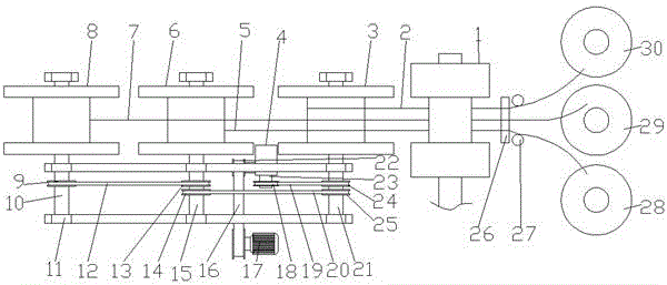
[0016] like figure 1 As shown, a multi-spool take-up system for a flattening machine includes a flattening machine 1, a guide device, a first pay-off reel 30, a second pay-off reel 29, a third pay-off reel 28, a first work Character wheel 3, the second I-shaped wheel 8, the third I-shaped wheel 6, frame 11, motor 17 and reduction box 4, said wire device includes two vertically arranged first cylindrical rollers 27 and is located on said second The second cylindrical roller 26 on the left side of a cylindrical roller 27 and horizontally arranged and parallel to the line of the two first cylindrical rollers 27, the first pay-off reel 30, the second pay-off reel 29 and the third pay-off reel The first copper wire 2, the second copper wire 7 and the third copper wire 5 are released correspondingly on the disc 28 respectively, and all pass through the wire device and then enter the flattening machine 1 to be rolled into flat copper wires; A first I-shaped wheel 3, a second I-shap...


PUM


Abstract

The invention discloses a multi-spool take-up system for a flatting mill and belongs to the field of take-up devices. The system comprises a flatting mill, a guiding device, a frame, a motor and a speed reducing box, wherein a first spool, a second spool and a third spool are arranged on the frame; a second chain disc and a third chain disc are fixed on a driving rod of the first spool, a fourth chain disc and a fifth chain disc are fixed on a driving rod of the second spool, and a sixth chain disc is fixed on a driving rod of the second spool; the motor and the speed reducing box are arranged below the frame, the motor is connected with the driving end of the speed reducing box through a first chain, the first chain disc and the second chain disc fixed on a non-driving end of the speed reducing box are connected by virtue of a second chain, the third chain disc is connected with the fifth chain disc by virtue of a third chain, and the fourth chain disc is connected with the sixth chain disc by virtue of a fourth chain. According to the system disclosed by the invention, the number of times of stopping to replace pay-off spools or spools is decreased, and moreover, actions of paying off and taking up for three times can be realized by using a motor which drives to take up and using the flatting mill, so that the production efficiency is improved and the production cost is lowered.

Description

technical field [0001] The invention belongs to the field of wire take-up devices, and more specifically relates to a multi-spool wire take-up system for a flattening machine. Background technique [0002] At present, the take-up device is mainly driven by the motor to rotate the I-shaped wheel to realize the take-up. The above structural method can control the rotation of the I-shaped wheel by controlling the rotation of the motor output shaft, thereby conveniently controlling the take-up speed. However, in the prior art, the steel wire take-up is mostly a single I-wheel rotation type take-up and discharge method. , with the improvement of equipment efficiency, at present, because the interval between wire take-up and replacement of I-shaped wheels is constantly shortened, a large amount of labor is added to steel wire manufacturers. At the same time, frequent replacement of I-shaped wheels not only delays production, but also increases labor intensity. , and the product q...

Claims


Application Information

Patent Timeline
Patent Type & Authority Applications(China)
IPC IPC(8): B21C47/04B21C47/34
Inventor 尚成荣
Owner 芜湖鑫泰铜业有限公司
Learn More