
Wideband amplifier circuit of Darlington structure

An amplifier circuit and amplifying circuit technology, applied in improving amplifiers to expand bandwidth, amplifying control, electrical components, etc., can solve the problems of inability to meet the bandwidth of broadband amplifiers, decreased gain performance, and high price, and achieve low cost and expandability. Bandwidth, the effect of solving the price

Active Publication Date: 2015-04-22
QINGDAO GOERTEK
View PDF5 Cites 4 Cited by
  • Summary
  • Abstract
  • Description
  • Claims
  • Application Information

AI Technical Summary

Problems solved by technology

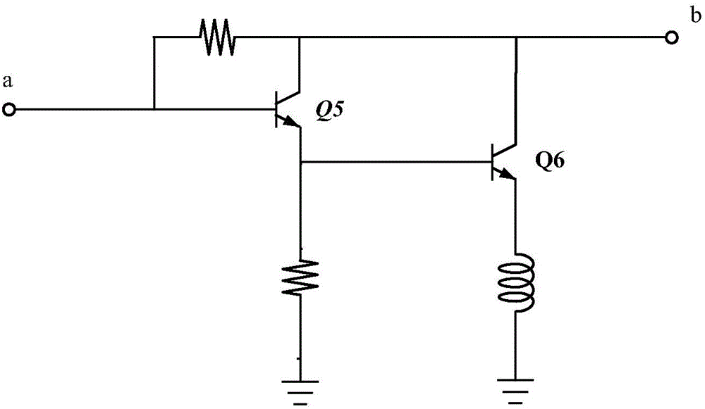
figure 1 It is a structural schematic diagram of a broadband amplifier circuit of a traditional Darlington structure, wherein a is the input end of the entire circuit, and b is the output end of the entire circuit, because the first-stage amplifying circuit (including Q5) and the second-stage amplifying circuit (including Q6) There is a 180-degree phase difference, so that the current of the output terminal b of the entire circuit is the difference between the collector current of the transistor Q5 and the collector current of the transistor Q6, resulting in a decrease in gain performance, so it is no longer possible to meet the wide bandwidth and high gain of the broadband amplifier. needs, and most of them use GaAs PHEMT process, which is expensive

Method used


Image

  • Wideband amplifier circuit of Darlington structure
  • Wideband amplifier circuit of Darlington structure
  • Wideband amplifier circuit of Darlington structure

Examples


Embodiment 1

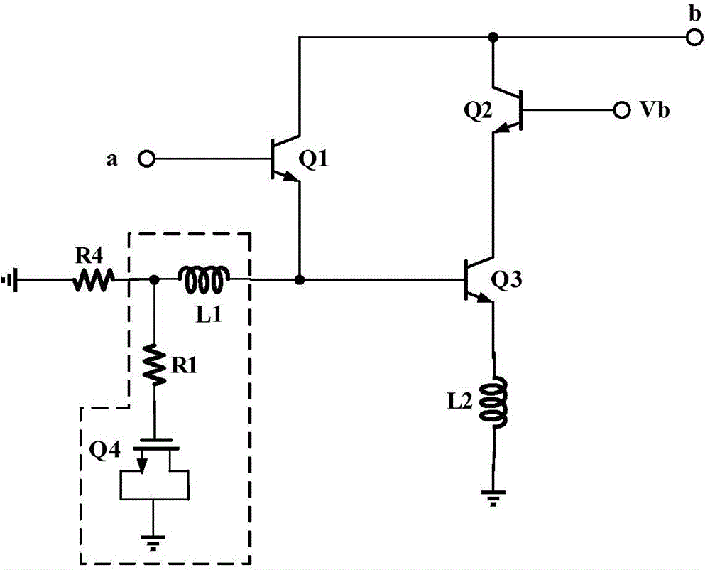
[0031] figure 2 It is a structural schematic diagram of Embodiment 1 of the present invention; as figure 2 As shown, the present invention discloses a Darlington structure broadband amplifier circuit, which includes: a first-stage amplifier circuit, a second-stage amplifier circuit and a phase adjustment circuit.

[0032] The first-stage amplifying circuit includes: a first triode Q1, and the base of the first triode is the signal input terminal a of the broadband amplifier circuit; the second-stage amplifying circuit includes: a second triode Q2 and a first transistor Q2 Three transistors Q3, the emitter of the second transistor Q2 is connected to the collector of the third transistor Q3, the base of the second transistor Q2 is connected to the DC bias voltage Vb; the third transistor Q3 The emitter is grounded.

[0033] The emitter of the first transistor Q1 is connected to the base of the third transistor Q3; the collector of the first transistor Q1 is connected to the ...

Embodiment 2

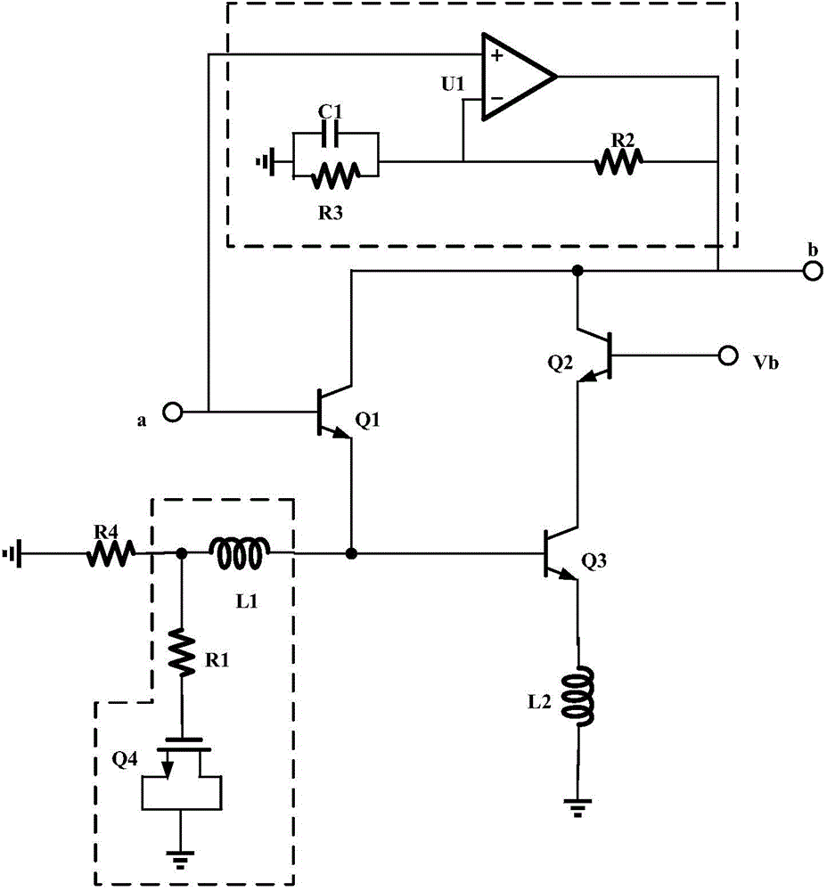
[0044] image 3 It is a structural schematic diagram of Embodiment 2 of the present invention. Such as image 3 As shown, a Darlington structure broadband amplifier circuit, the broadband amplifier circuit includes: a first-stage amplifier circuit, a second-stage amplifier circuit and a phase adjustment circuit.

[0045] The first-stage amplifying circuit includes: a first triode Q1, and the base of the first triode is the signal input terminal a of the broadband amplifier circuit; the second-stage amplifying circuit includes: a second triode Q2 and a first transistor Q2 Three transistors Q3, the emitter of the second transistor Q2 is connected to the collector of the third transistor Q3, the base of the second transistor Q2 is connected to the DC bias voltage Vb; the third transistor Q3 The emitter is grounded.

[0046] The emitter of the first transistor Q1 is connected to the base of the third transistor Q3; the collector of the first transistor Q1 is connected to the co...


PUM


Abstract

The invention discloses a wideband amplifier circuit of a Darlington structure. The wideband amplifier circuit comprises a first-stage amplification circuit, a second-stage amplification circuit and a phase regulating circuit. The first-stage amplification circuit comprises a first triode, and the base of the first triode is the signal input end of the wideband amplifier circuit. The second-stage amplification circuit comprises a second triode and a third triode. The emitter of the second triode is connected with the collector of the third triode, the base of the second triode is connected with direct-current bias voltages, and the emitter of the third triode is grounded. The emitter of the first triode is connected with the base of the third triode, and the collector of the first triode is connected with the collector of the second triode and serves as the signal output end of the wideband amplifier circuit. The phase regulating circuit is used for adjusting the current phase of the collector of the first-stage amplification circuit. One end of the phase regulating circuit is grounded, and the other end of the phase regulating circuit is connected with the connecting end of the emitter of the first triode and the base of the third triode.

Description

technical field [0001] The invention relates to the technical field of amplifier circuits, in particular to a Darlington-structure broadband amplifier circuit. Background technique [0002] The design of broadband amplifiers has become a hot issue in the field of monolithic microwave integrated circuits (MMICs) in modern electronic warfare. Negative Darlington structures are widely used in the design of broadband amplifier circuits. figure 1 It is a structural schematic diagram of a broadband amplifier circuit of a traditional Darlington structure, wherein a is the input end of the entire circuit, and b is the output end of the entire circuit, because the first-stage amplifying circuit (including Q5) and the second-stage amplifying circuit (including Q6) There is a 180-degree phase difference, so that the current of the output terminal b of the entire circuit is the difference between the collector current of the transistor Q5 and the collector current of the transistor Q6,...

Claims


Application Information

Patent Timeline
Patent Type & Authority Applications(China)
IPC IPC(8): H03F1/42H03G3/20
Inventor 陈金
Owner QINGDAO GOERTEK
Learn More