
Automatic tracking frame device of solar panel

An automatic tracking and solar panel technology, applied in the field of solar tracking, can solve the problems of complex structure, weak wind resistance, and unsightly appearance, and achieve the effect of high safety in use, strong wind resistance and simple structure

Inactive Publication Date: 2015-04-22
赖勋
View PDF7 Cites 2 Cited by
  • Summary
  • Abstract
  • Description
  • Claims
  • Application Information

AI Technical Summary

Problems solved by technology

[0004] But if this vertical automatic tracking frame is used in the family, for example, it will show many obvious defects when it is placed on the roof, terrace or verandah. The solar panels are basically upright or slightly tilted to receive the sunlight, which makes the windward side of the solar panels always large and high during the whole tracking process, resulting in weak wind resistance. Terraces or balconies are unsightly and unsightly; secondly, this kind of tracking frame needs to be driven by two shafts, which makes the structure complicated and increases the cost, hindering the popularization and use of solar energy utilization in the family

Method used


Image

  • Automatic tracking frame device of solar panel
  • Automatic tracking frame device of solar panel
  • Automatic tracking frame device of solar panel

Examples


Embodiment Construction

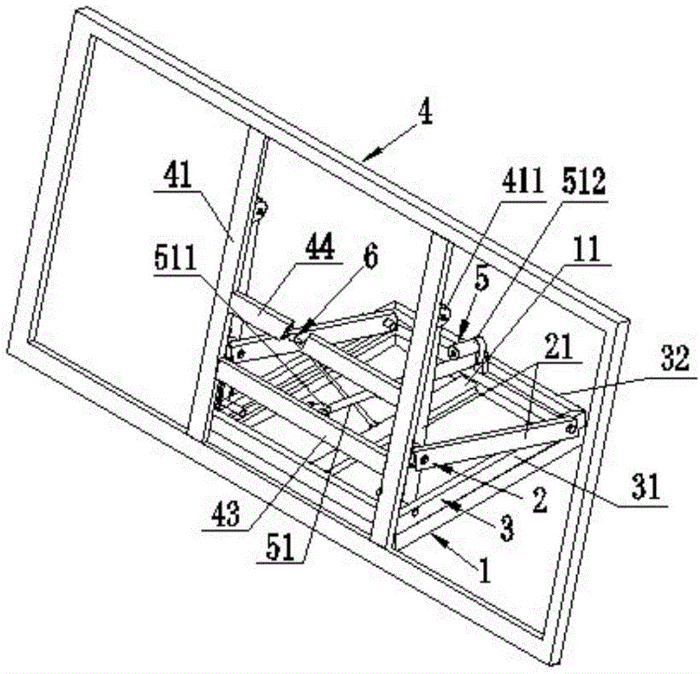
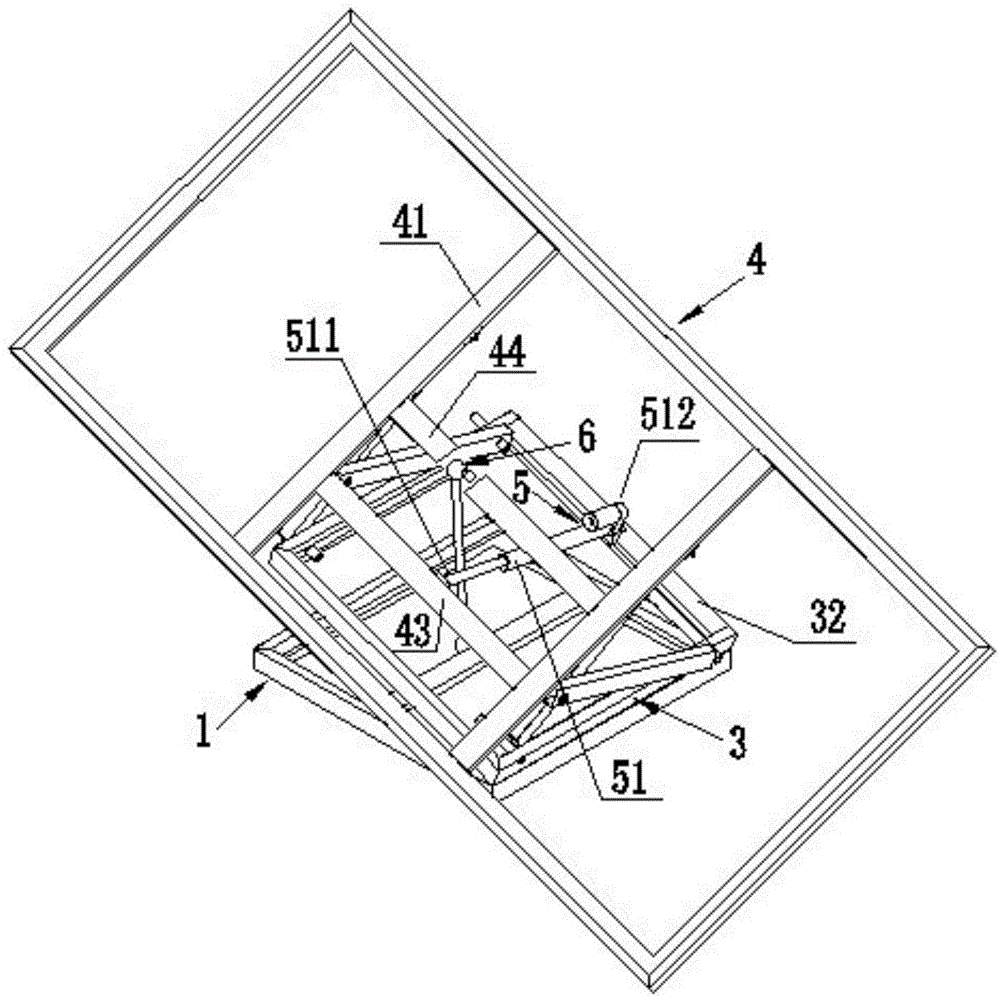
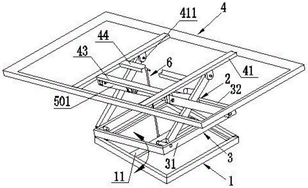
[0023] Such as figure 1 , a specific embodiment of the automatic tracking rack device of the present invention, it has a supporting plate support 4 for placing solar panels, a swing support 3 is provided below the supporting plate support 4, between the supporting plate support 4 and the swing support 3 It is connected by two pendulum units 2 placed in parallel. The swing rod unit 2 is composed of two cross-placed swing rods 21, the upper ends of the two swing rods 21 are hinged with the pallet bracket 4, and the lower end is hinged with the swing bracket 3, and the drive rod unit 5 is an electric ejector rod 50 (available on the market) , through the axial telescopic movement of the electric push rod 50, the swing rod 21 in the swing rod unit 2 swings, driving the pallet bracket 4 to swing in the tracking direction. In order to make the pallet bracket 4 swing in the tracking direction and also adjust the relative sun elevation angle, the swing bracket 3 is connected to the s...


PUM


Abstract

The invention relates to an automatic tracking frame device of a solar panel. The automatic tracking frame device comprises pendulum rod units, a swinging bracket, a supporting bracket, a linkage lever, a driving rod unit and a supporting plate bracket for placing the solar panel, wherein the swinging bracket is arranged below the supporting plate bracket, is connected with the supporting plate bracket by virtue of two parallel pendulum rod units, and is rotatably connected to the supporting bracket; the driving rod unit is connected with the supporting plate bracket to drive the supporting plate bracket to swing in a tracking direction; and one end of the linkage lever is hinged on the supporting bracket and the other end is hinged on the supporting plate bracket, and when the supporting plate bracket is driven by the driving rod unit to swing in the tracking direction, the linkage lever drives the supporting plate bracket to swing in an angle adjusting direction perpendicular to the swinging in the tracking direction. The automatic tracking frame device has the advantages of good rigidity, low amplitude of fluctuation, strong wind resistance and high use safety; linkage can be realized by virtue of tracking swinging and elevation adjustment swinging, so that the automatic tracking frame device can be driven by a single shaft, is simple in structure and low in cost and is more suitable for being used by families.

Description

technical field [0001] The invention relates to solar tracking technology, in particular to a solar panel automatic tracking frame device. Background technique [0002] At present, the solar panel automatic tracking frame generally adopts a vertical design, that is, the solar panel mainly follows the horizontal rotation of the vertical axis to track the sun, and at the same time, it can also perform vertical rotation with its own horizontal axis to adjust the elevation angle relative to the sun. This kind of automatic tracking frame Generally, it is necessary to drive the rotation of two rotating shafts. [0003] The reason why the vertical automatic tracking frame is generally used at present is based on the understanding that the vertical automatic tracking frame is relatively easy to be designed as a mechanism with a simple structure, thereby making the cost low. [0004] But if this vertical automatic tracking frame is used in the family, for example, it will show many ...

Claims


Application Information

Patent Timeline
Patent Type & Authority Applications(China)
IPC IPC(8): G05D3/00
Inventor 赖勋
Owner 赖勋
Learn More