
Broadband optical frequency comb generating system based on phase lock control

An optical frequency comb and phase-locked technology, applied in the field of microwave photonics, can solve problems such as instability and achieve the effect of overcoming bandwidth

Active Publication Date: 2015-04-22
INST OF SEMICONDUCTORS - CHINESE ACAD OF SCI
View PDF4 Cites 16 Cited by
  • Summary
  • Abstract
  • Description
  • Claims
  • Application Information

AI Technical Summary

Problems solved by technology

However, these methods are unstable and require high-frequency microwave sources

Method used


Image

  • Broadband optical frequency comb generating system based on phase lock control

Examples


Embodiment Construction

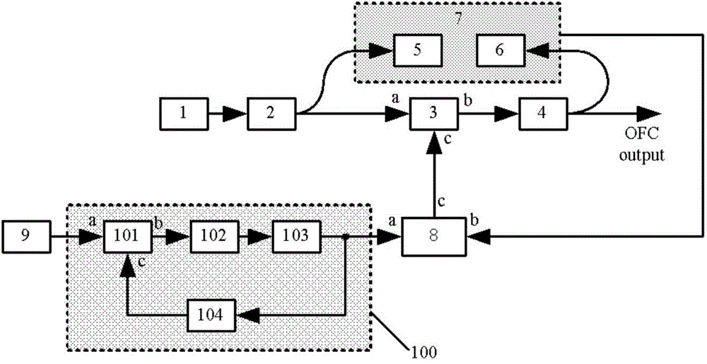
[0017] see figure 1 As shown, the present invention provides a generation system based on a phase-locked control broadband optical frequency comb, comprising:

[0018] A stable broadband optical frequency comb generation system based on phase-locked control, comprising:

[0019] A narrow linewidth laser 1, which is used to provide a coherent seed light source, the narrow linewidth laser 1 is a semiconductor laser or a fiber laser in the form of tuned wavelength;

[0020] An optical beam splitter 2, the input end of which is connected to the output end of the narrow-linewidth laser 1, is used to divide the seed light source into two paths, wherein the optical signal of one path is output to the optical phase modulator behind for loading electrical signals , the other optical signal is used for inputting to the first photodetector 5 for photoelectric detection and then used for subsequent phase identification;

[0021] An FP cavity electro-optic phase modulator 3, the optical ...


PUM


Abstract

Provided is a broadband optical frequency comb generating system based on phase lock control. The broadband optical frequency comb generating system comprises a narrow linewidth laser, optical splitters, a FP cavity electro-optic phase modulator, a first photoelectric detector, a second photoelectric detector, a bias Tree, a referential microwave signal and a point phase lock controlling module. A connection in the sequence of the optical splitter, the FP cavity electro-optic phase modulator, the optical splitter, the first photoelectric detector, the second photoelectric detector, the bias Tree, the referential microwave signal and the point phase lock controlling module is established. An input end of a phase lock controlling device is connected with an output end of the referential microwave signal, and an output end of the phase lock controlling device is connected with an input port a of the bias Tree. According to the broadband optical frequency comb scheme generated on the basis of an electric phase lock control method, the difficulties in the aspects such as the bandwidth, the weight, the volume and the electromagnetic compatibility in the traditional method are solved.

Description

technical field [0001] The invention belongs to the field of microwave photonics, in particular to a broadband optical frequency comb generation system based on phase-locked control. Background technique [0002] In order to realize the connection between microwave frequency and optical frequency, people have proposed a frequency chain scheme very early. The main idea is to convert optical frequency to microwave frequency through nonlinear frequency conversion and other means. Due to the complex technical process and low nonlinear efficiency of this scheme, scientists did not build such a device until the end of the 20th century after more than ten years of hard work. However, the huge volume structure of the frequency chain and the accumulated errors caused by multiple conversions determine the complexity and uncertainty of measuring optical frequency with it. In 2005, the Nobel Prize winner proposed the concept of optical frequency comb, which is also a new concept for ma...

Claims


Application Information

Patent Timeline
Patent Type & Authority Applications(China)
IPC IPC(8): G02F1/35G02F1/03H01S3/10
CPCG02F1/21G02F1/353G02F1/213H01S3/10084
Inventor 孙文惠刘建国袁海庆王玮钰王文亭佟有万王欣祝宁华
Owner INST OF SEMICONDUCTORS - CHINESE ACAD OF SCI
Learn More