Lens array and PD array high-precision alignment mounting device and alignment method thereof

A lens array and patch device technology, applied in the field of optical communication, can solve the problems of large judgment errors, human errors, and high maintenance costs, and achieve the effect of ensuring consistency

Active Publication Date: 2015-04-22
GUANGXUN SCI & TECH WUHAN
View PDF5 Cites 39 Cited by
  • Summary
  • Abstract
  • Description
  • Claims
  • Application Information

AI Technical Summary

Problems solved by technology

In the operation of the patch, the human eye is used to judge whether the center of the lens array coincides with the center of the photosensitive surface of the PD array. This method has a large human error in judging the center of the two, and the repeatability is not good; PD array, whose photosensitive surface is only tens of microns, makes the judgment error of center alignment larger. On the other hand, high-precision placement machines are expensive and maintenance costs are also high

Method used


Image

  • Lens array and PD array high-precision alignment mounting device and alignment method thereof
  • Lens array and PD array high-precision alignment mounting device and alignment method thereof
  • Lens array and PD array high-precision alignment mounting device and alignment method thereof

Examples


Embodiment Construction

[0043] Below in conjunction with accompanying drawing, the present invention is described in further detail;

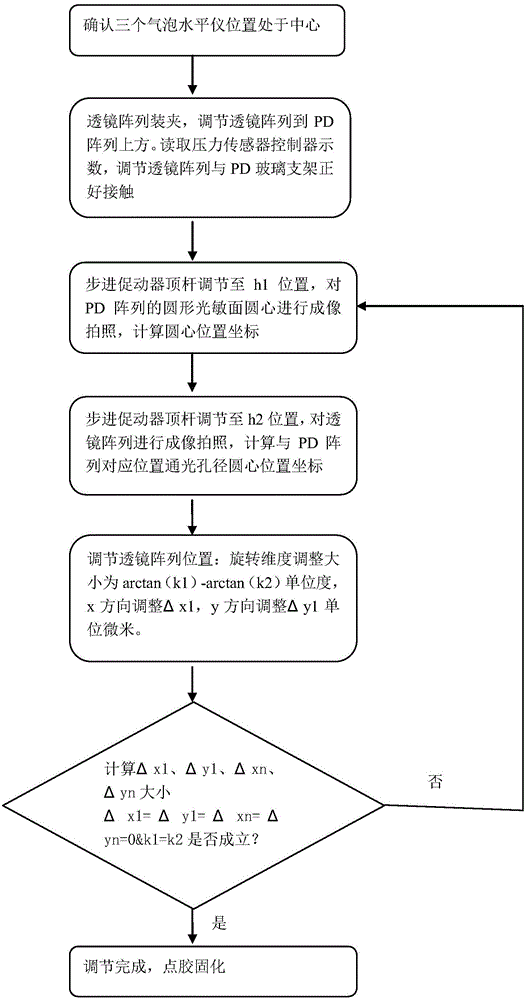
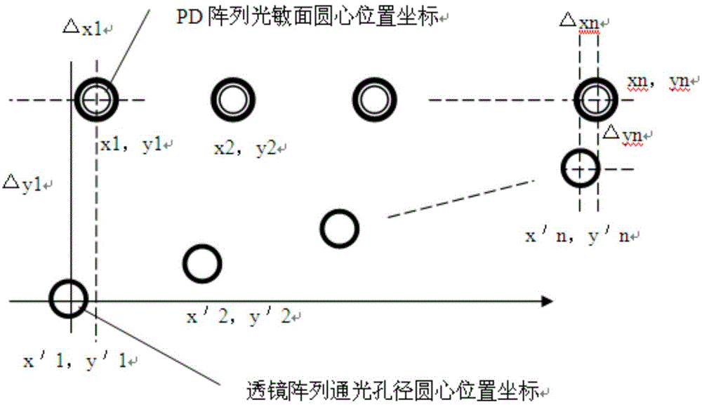
[0044] The patent of the present invention provides a method for high-precision alignment of the lens array 121 and the PD array 118, which uses automatic image processing technology to find the center of the circle, and has the characteristics of high precision, good repeatability, and high degree of automation. This method is also applicable to the coupling alignment of the lens array 121 and the laser array.

[0045] In the patent "Optical waveguide chip and PD array lens coupling device" (application number: 201310433022.2), the coupling between the waveguide chip and the PD array 118 uses the lens array 121 to converge the optical signal. The patch structure of the lens array 121 and the PD array 118 is used as an example to illustrate how to use automatic image processing technology to realize high-precision patch alignment of the lens array 121 and the PD array...


PUM


Abstract

The invention relates to a lens array and PD array high-precision alignment mounting device and an alignment method of the lens array and PD array high-precision alignment mounting device. The alignment method comprises the steps of adjusting the expansion link of a stepping booster until the photosensitive surface of the PD array passes through the lens array to be clearly imaged on an image acquisition CCD (Charge Coupled Device), recording the adjusting distance h1 of the expansion link of the stepping booster, acquiring the position coordinates (xn, yn) of the circular center of each circular photosensitive surface of the PD array in the image and computing the slope k1 of the connecting line of the circular centers of the photosensitive surfaces; adjusting the stepping booster again, enabling the lens array to be imaged in an image acquisition CCD viewing field clearly, recording the adjusting distance h2 of the expansion link of the stepping booster, acquiring the position coordinates (x'n, y'n) of the circular center of a clear aperture of the lens array corresponding to the PD array, and computing the slope k2 of the connecting line of the circular centers of the clear apertures of the lens arrays; adjusting a high-precision fine adjustment frame to adjust the position of the lens array according to the calculated values of deltaxn, deltayn and arctan(k1)-arctan(k2); and repeating the operations until meeting the following conditions: deltaxn and deltayn are both equal to 0 and K1 is equal to k2. The device and the method can realize mounting alignment automation of the lenses.

Description

technical field [0001] The invention belongs to the field of optical communication, relates to a photoelectric module in the optical communication technology, and is especially suitable for realizing high-precision alignment of a lens array and a photodiode array (Photodiode, PD) or a laser array and an alignment method thereof. Background technique [0002] Automated image processing technology is widely used in all walks of life, from automatic reading and tracing of barcodes on production lines, automatic identification of license plates, automatic defect detection of parts, DVD identification and automatic return to guiding robots for equipment assembly, etc., image processing technology is play a huge role. The wide application of image processing technology is mainly due to the characteristics of image processing technology such as intelligence, stability, good repeatability, and high precision, which can replace a large amount of manual and repetitive labor. It is pre...

Claims


Application Information

Patent Timeline
Patent Type & Authority Applications(China)
IPC IPC(8): G01C15/00G02B6/42
CPCG02B6/4219G02B6/4221G02B6/4224G02B6/4204G02B6/4227G02B6/4239G02B6/4206
Inventor 石川习华丽江雄梁雪瑞尹华林马卫东
Owner GUANGXUN SCI & TECH WUHAN
Why Eureka
Try Eureka