
Automatic bullet warhead collecting device

A technology of automatic collection and bullets, which is applied in the field of firearms, can solve the problems of personal injury, and achieve the effect of fast retrieval of bullets, simple operation and low cost

Active Publication Date: 2015-04-22
卡目索纳智能科技研发(江苏)有限公司
View PDF6 Cites 11 Cited by
  • Summary
  • Abstract
  • Description
  • Claims
  • Application Information

AI Technical Summary

Problems solved by technology

[0003] At present, some bullet collection devices produced in China have not yet achieved satisfactory results in terms of personal safety of operators, and often cause personal injuries

Method used


Image

  • Automatic bullet warhead collecting device
  • Automatic bullet warhead collecting device
  • Automatic bullet warhead collecting device

Examples


Embodiment 1

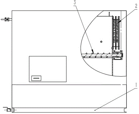
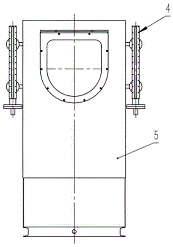
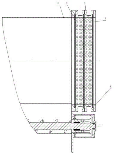
[0030] See attached figure 1 , 2 As shown, an automatic collection device for bullets and warheads, the automatic collection device for bullets and warheads mainly includes a frame 1, a bullet-stopping port assembly 2, an automatic bullet-retracting assembly 3, a bullet-stopping barrel 10, a liquid level display and control system 4 and Cover 5; wherein, the cover 5 is installed on the frame 1, the bullet-resistant tube 10, the bullet-resistant port assembly 2 and the automatic bomb-retracting assembly 3 are arranged in the cover 5, the liquid level display and control system 4 and the bullet-resistant tube 10 communicates with each other and is installed on the outside of the casing 5. The bullet-resistant cylinder 10 is a U-shaped structure with a buffer liquid medium inside. The bullet-resistant cylinder 10 is placed horizontally inside the casing 5. The bullet-resistant port assembly 2 and the automatic bullet-retracting assembly 3 Connected with the bullet-resisting cyli...

Embodiment 2

[0034] See attached figure 1 , 2 As shown, an automatic collection device for bullets and warheads, the automatic collection device for bullets and warheads mainly includes a frame 1, a bullet-stopping port assembly 2, an automatic bullet-retracting assembly 3, a bullet-stopping barrel 10, a liquid level display and control system 4 and Cover 5; wherein, the cover 5 is installed on the frame 1, the bullet-resistant tube 10, the bullet-resistant port assembly 2 and the automatic bomb-retracting assembly 3 are arranged in the cover 5, the liquid level display and control system 4 and the bullet-resistant tube 10 communicates with each other and is installed on the outside of the casing 5. The bullet-resistant cylinder 10 is a U-shaped structure with a buffer liquid medium inside. The bullet-resistant cylinder 10 is placed horizontally inside the casing 5. The bullet-resistant port assembly 2 and the automatic bullet-retracting assembly 3 Connected with the bullet-resistant cyli...

Embodiment 3

[0038] On the basis of Embodiment 1 or 2, as a further solution of the present invention: the elastic water blocking baffle is composed of more than two layers of methyl vinyl silicone rubber with a hardness of 40-70 Shore.


PUM

PropertyMeasurementUnit
Hardnessaaaaaaaaaa

Abstract

The invention discloses an automatic bullet warhead collecting device and belongs to the technical field of fire arms. The automatic bullet warhead collecting device mainly comprises a rack, a bullet stopping opening assembly, an automatic bullet collecting assembly, a liquid level display and control system and a housing part. Compared with the prior art, the automatic bullet warhead collecting device has the following advantages that grazing fire is adopted, water (liquid) media are used for collecting bullet warheads, and therefore bullets can be taken conveniently and fast; automatic bullet collecting and fast bullet taking can be achieved through the device; the control system is automatic, operation is easy, and control is convenient; bullet shooting and collecting of the device are convenient to collect, side continuous shooting can be achieved, and the warheads can be taken conveniently and fast without obstacles; the size of a water bullet grasping device is minimized, and the warheads can be taken more conveniently and scientifically; the whole device is low in manufacturing cost, convenient to manufacture, easy to disassemble and beneficial for wide application and popularization.

Description

technical field [0001] The invention discloses an automatic collection device for bullets and warheads, which belongs to the technical field of firearms. Background technique [0002] The bullet collection device is a device suitable for recovering the fired bullets and preventing the movement of the bullets during actual shooting, so as to effectively avoid damage to the shooting site and the surrounding environment due to shooting. At the same time, it also plays a certain protective role relative to the safety of the shooting personnel themselves. [0003] At present, some bullet collection devices produced in China have not yet achieved satisfactory results in terms of the personal safety of operators, and often cause personal injuries. Yet the progress of relevant technicians in this respect is stagnant again, so just be badly in need of a kind of such device equipment on the market to guarantee the safety of operator. The device conforms to the market demand and can ...

Claims


Application Information

Patent Timeline
IPC IPC(8): F41J13/00
CPCF41J13/00
Inventor 潘楠刘益杨敬树
Owner 卡目索纳智能科技研发(江苏)有限公司
Learn More