
E-shaped magnetic core gum application tool

A magnetic core and adhesive technology, which is applied in the direction of mechanical equipment, connecting components, etc., can solve the problems of low efficiency of the adhesive method

Inactive Publication Date: 2015-04-22
河南普照光电科技有限公司
View PDF6 Cites 2 Cited by
  • Summary
  • Abstract
  • Description
  • Claims
  • Application Information

AI Technical Summary

Problems solved by technology

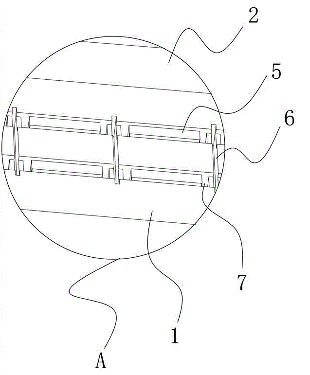
The bonding process of the insulating tape is as follows: First, put each E-shaped magnetic core into a magnetic core installation mold with multiple magnetic core accommodation slots. There are two positioning columns in the magnetic core accommodation slots, so that the E-shaped After the magnetic core is buckled on the positioning column, there are gaps between the four circumferential surfaces of the E-shaped magnetic core and the groove wall of the magnetic core accommodating groove. The top of the E-shaped magnetic There is a cutting groove between the grooves, which is convenient for the cutter to cut the insulating tape. After the E-shaped magnetic core is fixed, the insulating tape is pasted on the E-shaped magnetic core, and then the insulating tape between the E-shaped magnetic cores is cut off with a knife, and the Each E-shaped magnetic core is taken out from the magnetic core holding groove, and then the parts of the insulating tape that protrude from the upper surface of the E-shaped magnetic core are pressed to the other four surfaces by hand one by one to complete the adhesive process. This adhesive method is very inefficient

Method used


Image

  • E-shaped magnetic core gum application tool
  • E-shaped magnetic core gum application tool
  • E-shaped magnetic core gum application tool

Examples


Embodiment Construction

[0012] The technical solutions of the present invention will be described in further detail below through specific implementation methods.

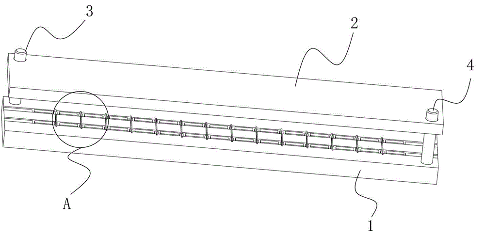
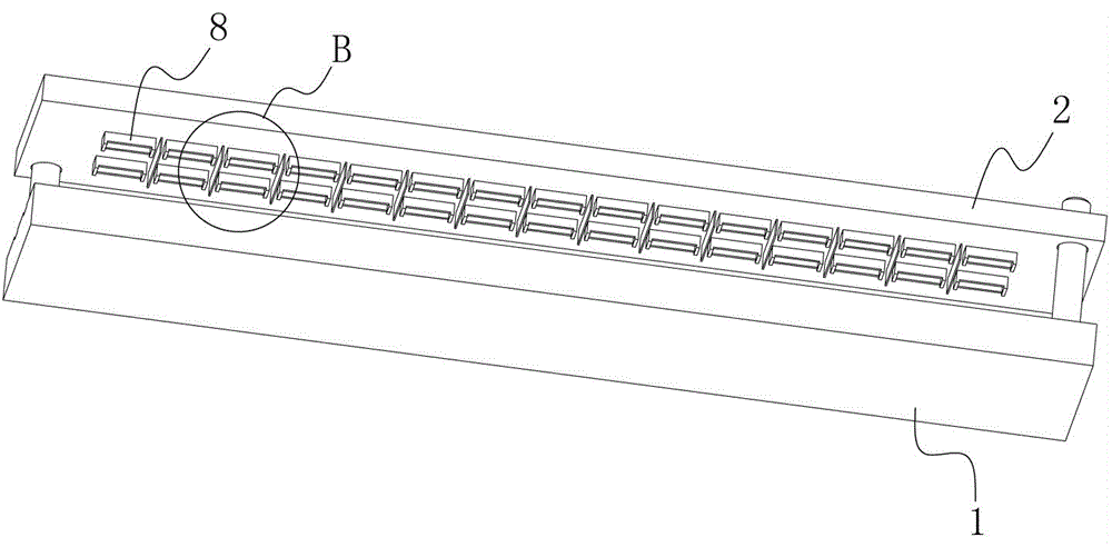
[0013] Examples of adhesive tooling for E-shaped magnetic cores, such as Figure 1-4 As shown, it includes a magnetic core installation mold 1 with a plurality of magnetic core accommodation grooves 7. In this embodiment, there are two rows of magnetic core accommodation grooves 7, and each row has fifteen magnetic core accommodation grooves 7. In other implementations In the example, it can be increased or decreased as required, there are two positioning columns (not shown in the figure) in the magnetic core accommodation groove 7, there is a cutting groove 6 between two adjacent magnetic core accommodation grooves 7, and the magnetic core installation mold 1 There are two guide columns 3, 4 on the guide column, and the mold upper cover 2 slides through the guide column. A plurality of extruded parts 8 are arranged on the lower surface o...


PUM


Abstract

The invention provides an E-shaped magnetic core gum application tool. The E-shaped magnetic core gum application tool comprises a magnetic core installation mold provided with multiple magnetic core containing grooves. Positioning columns are arranged in the magnetic core containing grooves. A cutting groove is formed between every two adjacent magnetic core containing grooves. At least two guide columns are arranged on the magnetic core installation mold. An upper mold cover penetrates through the guide columns in a sliding mode. Multiple extrusion pieces are arranged on the lower surface of the upper mold cover. The extrusion pieces are provided with inner cavities matched with E-shaped magnetic cores in an inserted mode and outer circumferential surfaces matched with the corresponding magnetic core containing grooves in an inserted mode, a cutting tool matched with the corresponding cutting groove in a cutting mode is arranged between every two adjacent extrusion pieces, and the blade portions of the cutting tools are lower than the bottoms of the extrusion pieces. The guide columns are arranged on the magnetic core installation mold, the upper mold cover penetrates through the guide columns in the sliding mode, the extrusion pieces are arranged on the lower surface of the upper mold cover, and through the tool, one person can apply gum to the E-shaped magnetic cores at a time, and work efficiency is improved dozens of times and even hundreds of times.

Description

technical field [0001] The invention relates to a magnetic core adhesive tooling, in particular to an E-shaped magnetic core adhesive tooling. Background technique [0002] The current E-shaped magnetic core needs to insulate the other five surfaces except one side of the opening. Since the general insulating coating is easy to be broken down, in order to meet the insulation requirements, the insulation treatment is often carried out by adhesive, that is, insulating tape is pasted on the five sides of the E-shaped magnetic core. The bonding process of the insulating tape is as follows: First, put each E-shaped magnetic core into a magnetic core installation mold with multiple magnetic core accommodation slots. There are two positioning columns in the magnetic core accommodation slots, so that the E-shaped After the magnetic core is buckled on the positioning column, there are gaps between the four circumferential surfaces of the E-shaped magnetic core and the groove wall of...

Claims


Application Information

Patent Timeline
IPC IPC(8): F16B11/00
CPCF16B11/00
Inventor 刘金凯甘朋
Owner 河南普照光电科技有限公司
Learn More