
Rigid connector of offshore buoyancy tank system

A technology of rigid connection and floating tank, which is applied in the direction of thin plate connection, connection components, mechanical equipment, etc., can solve the problems of affecting operation, inconvenient maintenance, high manufacturing cost, etc., and achieves improved reliability and convenience, simple and convenient maintenance, better effect

Active Publication Date: 2015-04-22
TIANJIN TDBH NAVAL ARCHITECTURE & OCEAN ENG ACADEMY
View PDF8 Cites 1 Cited by
  • Summary
  • Abstract
  • Description
  • Claims
  • Application Information

AI Technical Summary

Problems solved by technology

However, this rigid connection joint has many disadvantages: 1) There are many structural parts, the structure is complex, and the manufacturing cost is high; 2) The butterfly connector is a built-in mechanism, which is very inconvenient to maintain; 3) Butterfly connection in the shallow water area of ​​the beach The device is easily blocked by sand, which affects the operation; 4) The seal between the pull rod and the floating tank in the butterfly arm box is easily damaged, causing water to enter the floating tank

Method used


Image

  • Rigid connector of offshore buoyancy tank system
  • Rigid connector of offshore buoyancy tank system
  • Rigid connector of offshore buoyancy tank system

Examples


Embodiment Construction

[0023] In order to further understand the invention content, characteristics and effects of the present invention, the following examples are given, and detailed descriptions are as follows in conjunction with the accompanying drawings:

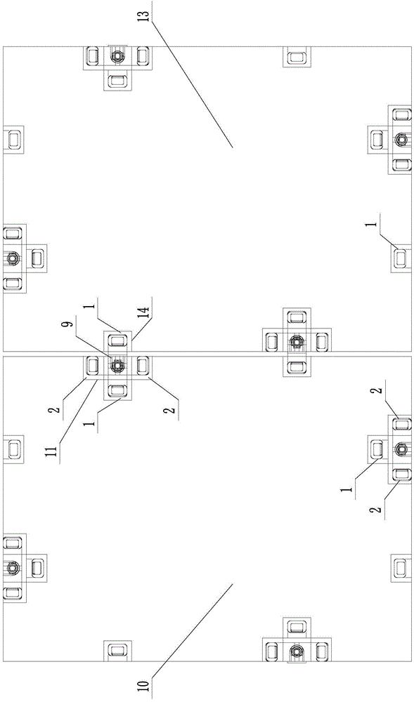
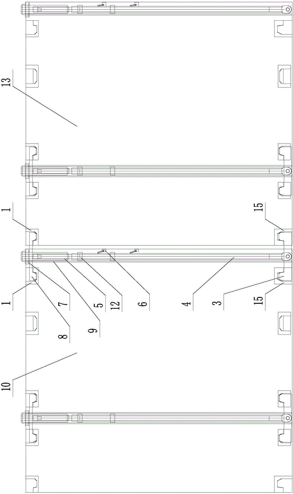
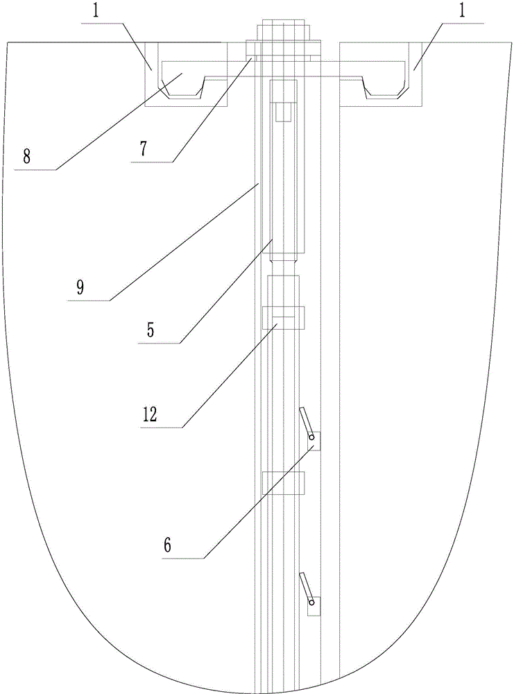
[0024] see Figure 1 ~ Figure 4 , a rigid connection joint of a marine buoyancy tank system, including a tie rod 4, which is installed in a vertical passage 9, and the vertical passage 9 is bent into a U shape by a steel plate and welded on the side of the buoyancy tank A10 Formed on the inside of the riser.

[0025] The lower end of the pull rod 4 is provided with a strip-shaped lower wedge hook 3 perpendicular to it, the middle part of the lower wedge hook 3 is hinged with the lower end of the pull rod 4, and a bar is respectively arranged on the two ends of the lower wedge hook 3. Wedge-shaped hook head; the limit sleeve 12 is fixedly connected on the pull rod 4; the upper end of the pull rod 4 is provided with a cylindrical nut 5 threade...


PUM


Abstract

The invention discloses a rigid connector of an offshore buoyancy tank system. The rigid connector comprises a pulling rod which is arranged in a vertical channel in a penetrating mode. A lower wedge hook is arranged at the lower end of the pulling rod. A limiting sleeve is fixedly connected with the pulling rod. A cylindrical nut is arranged at the upper end of the pulling rod. A strip-shaped upper wedge hook is arranged on the cylindrical nut in a sleeved mode. The upper wedge hook and the lower wedge hook are arranged symmetrically up and down. At least two wedge hook storing bases and at least two upper wedge hook connecting bases are arranged below the upper wedge hook. One upper wedge hook connecting base and two upper wedge hook storing bases are fixed on the upper face of a buoyancy tank A. The other upper wedge hook connecting base is fixed on the upper face of a buoyancy tank buoyancy tank B. Two lower wedge hook storing bases and two lower wedge hook connecting bases are arranged above the lower wedge hook. A limiter matched with a limiting sleeve is fixed on the buoyancy tank A. All splicing operation can be carried out on the upper surfaces of the buoyancy tanks, maintaining of the connector is carried out on the outer portions of the buoyancy tanks, easiness and convenience are achieved, the structure is simple, and manufacturing cost is low.

Description

technical field [0001] The invention relates to a connection mechanism of equipment, in particular to a rigid connection joint of an offshore buoyancy tank system. Background technique [0002] Patent document CN2871946, on February 21, 2007, disclosed a rigid connection joint for a buoyant tank system that facilitates the assembly of buoyant tanks in sea wind and waves, including a slider connector for the upper connection of the buoyant tank and a module for the buoyant tank. The butterfly connector connected at the bottom is characterized by: slider connector, composed of slider seat A, slider seat B, double-ear slider, single-ear slider, pin shaft, positioning device, brake block and eyebolt screw , the slider seat A and the slider seat B are both open at both ends, and there are two plug holes on the top. The single-ear slider and the double-ear slider can be connected by a cylindrical pin to form a slider connector. Assemblies, the slider penetrates into the slider se...

Claims


Application Information

Patent Timeline
IPC IPC(8): F16B5/00
CPCF16B5/0004
Inventor 谷峰孙桢王广东
Owner TIANJIN TDBH NAVAL ARCHITECTURE & OCEAN ENG ACADEMY
Learn More