High-power diesel brushless direct current motor speed regulating actuator
A brushless DC motor and high-power diesel engine technology, applied in machine/engine, mechanical equipment, engine control, etc., can solve the problems of complex design, high price and cost, and complicated control of limited torque motors, and achieve compact structure and low maintenance. The effect of low cost and high control precision
- Summary
- Abstract
- Description
- Claims
- Application Information
AI Technical Summary
Problems solved by technology
Method used
Image
Examples
Embodiment example 1
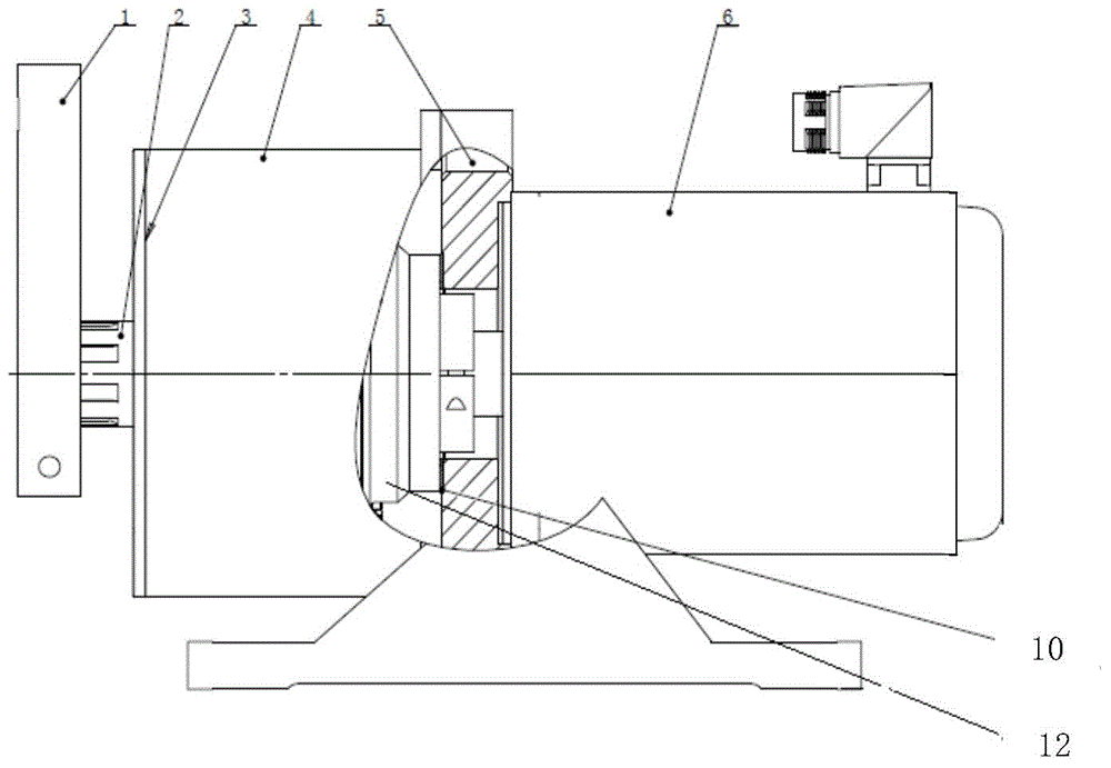
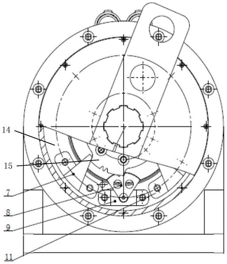
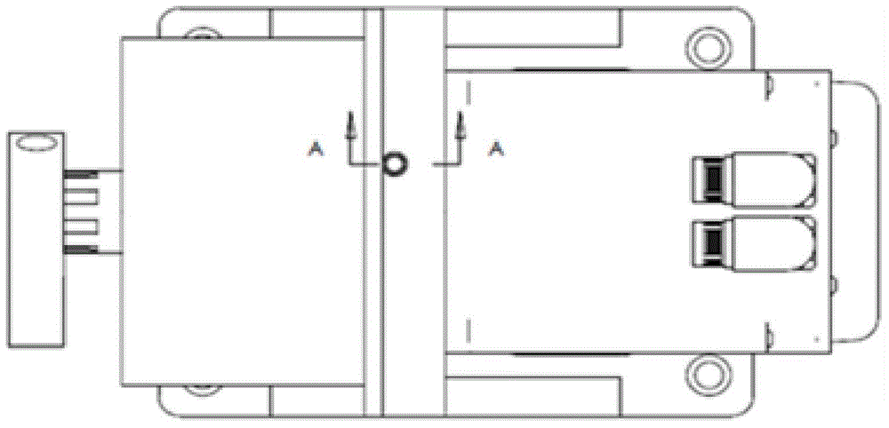
[0020] Implementation Case 1: Combining figure 1 and figure 2 , the present invention includes an inverted T-shaped bracket 5, a DC brushless motor 6 installed on one side of the inverted T-shaped bracket 5, and a guide sleeve 4 installed on the other side of the inverted T-shaped bracket 5, and an end cover is installed on the end of the guide sleeve 4 3. A flange 14 is arranged inside the guide sleeve 4, and the right end surface of the flange 14 is fixedly connected to one end of the reducer 12, and the other end of the reducer 12 is installed on the inverted T-shaped bracket 5, that is, the reducer 12 adopts The double fixing method ensures the strength of the present invention. The output shaft of the brushless DC motor 6 is connected to the input shaft of the reducer 12 through a coupling, and the output shaft of the reducer 12 is connected to the main shaft 2, and the large sector gear is set on the main shaft 2. 15 and the main shaft 2 is integrated with the large se...
Embodiment example 2
[0022] Implementation Case 2: Based on the above implementation cases, the present invention is respectively equipped with a left limit stopper 7 and a right limit stopper 11 on both sides of the sensor bracket 9 on the left end surface of the flange 14. The position of the stopper can be adjusted so that the maximum output angle of the main shaft 2 can be adjusted and limited, which can prevent the main shaft 2 from continuing to move due to inertia, limit the range of rotation angle of the main shaft 2, and improve the control accuracy. The sensor bracket 5 of the present invention, the left limit block 7 and the right limit block 11 are all installed in the guide sleeve 4, fastened on the flange end face of the guide sleeve 4 with screws, and sealed with the end cover 3.
Embodiment example 3
[0023] Implementation case three: Based on the above-mentioned implementation cases, the present invention sets a mouth plate 10 on the end face of the reducer 12 in contact with the inverted T-shaped bracket 5, and through the joints between the mouth plate 10 and the motor 6, the mouth plate 10 and the reducer 12 The spigot is centered to ensure that the reducer 12 is coaxial with the brushless DC motor 6 .
PUM
 Abstract
Description
Claims
Application Information
 - R&D
- Intellectual Property
- Life Sciences
- Materials
- Tech Scout
- Unparalleled Data Quality
- Higher Quality Content
- 60% Fewer Hallucinations
Browse by: Latest US Patents, China's latest patents, Technical Efficacy Thesaurus, Application Domain, Technology Topic, Popular Technical Reports.
© 2025 PatSnap. All rights reserved.Legal|Privacy policy|Modern Slavery Act Transparency Statement|Sitemap|About US| Contact US: help@patsnap.com


