
Subarea power supply system and subarea power supply method for wet electric precipitator

A technology of wet electrostatic precipitator and power supply system, applied in the direction of power supply technology, electrostatic separation, external electrostatic separator, etc., can solve the problems of small dust particle size, electric field paralysis, and large flue gas volume, so as to reduce operation risk, Effect of improving dust removal efficiency and reducing load

Inactive Publication Date: 2015-04-22
SHANGHAI LONGKING ENVIRONMENTAL PROTECTION
View PDF9 Cites 9 Cited by
  • Summary
  • Abstract
  • Description
  • Claims
  • Application Information

AI Technical Summary

Problems solved by technology

[0006] Usually, the wet electrostatic precipitator uses a high-voltage power supply device to supply high-voltage electricity to the entire dust removal electric field, and provides all the electric energy required for charging and collecting flue gas dust. Small and difficult to remove and other characteristics, the high-voltage power supply has a large load, and once the power supply fails, it will cause the entire electric field to be paralyzed and the wet electrostatic precipitator to stop operating

Method used


Image

  • Subarea power supply system and subarea power supply method for wet electric precipitator
  • Subarea power supply system and subarea power supply method for wet electric precipitator
  • Subarea power supply system and subarea power supply method for wet electric precipitator

Examples


Embodiment Construction

[0045] In order to explain the embodiments of the present invention or the technical solutions in the prior art more clearly, the specific embodiments of the present invention will be described below with reference to the drawings. Obviously, the drawings in the following description are only some embodiments of the present invention. For those of ordinary skill in the art, without creative work, other drawings can be obtained based on these drawings and obtained Other embodiments.

[0046] In order to make the drawings concise, the figures only schematically show the parts related to the present invention, and they do not represent the actual structure of the product. In addition, in order to make the drawings concise and easy to understand, in some drawings, only one of the components with the same structure or function is schematically shown, or only one of them is marked. In this article, "a" not only means "only this one", but can also mean "more than one".

[0047] In the f...


PUM


Abstract

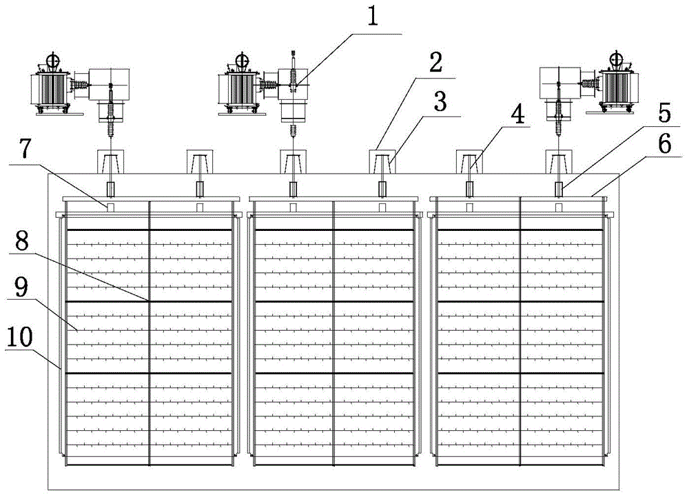
The invention provides a subarea power supply system and a subarea power supply method for a wet electric precipitator. The subarea power supply system for the wet electric precipitator comprises a plurality of electric field subareas, wherein each electric field subarea comprises a cathode hanger, a cathode frame, a cathode line, an anode beam and an anode plate. The system also comprises power supply sub-systems with the same number as the electric field subareas, wherein each power supply sub-system comprises a high-voltage power supply device, a low-voltage power supply device and an insulator box. Cathode structures between the electric field subareas are mutually separated from each other, and each electric field subarea is independently supplied by power. The subarea power supply method comprises the steps that: each electric field subarea is respectively and independently equipped with the high-voltage power supply device and the insulator box; the cathodes structures between different electric field subareas are mutually disconnected, and the safe distance is ensured, so that each subarea is independently discharged; the drying and insulation of high-voltage incoming lines is ensured by a continuous hot wind blowing mode. The subarea power supply system and the subarea power supply method provided by the invention have the advantages of effectively ensuring the safe and stable operation of the wet electric precipitator, effectively improving the dedusting efficiency, reducing the risk and reducing the high-voltage power supply load.

Description

Technical field [0001] The invention relates to the technical field of flue gas treatment methods, in particular to a partitioned power supply system and a partitioned power supply method for a wet electrostatic precipitator. Background technique [0002] my country's coal-based energy structure will not change for a long time. As the country continues to improve the exhaust dust emission standards of coal-fired boilers, the dust emission requirements have been greatly increased to 10mg / Nm 3 Even lower, while the SO carried in the flue gas after wet desulfurization 3 Aerosols and "gypsum rain" particles have also become new sources of pollution, and the need for deep dust removal technology is imminent. [0003] At present, common dry-type electrostatic precipitators, electric-bag compound precipitators and bag-type precipitators are used as front-end dust control technologies, which cannot effectively guarantee the ultra-clean emission of flue gas dust after the desulfurization de...

Claims


Application Information

Patent Timeline
Patent Type & Authority Applications(China)
IPC IPC(8): B03C3/66B03C3/16
Inventor 张小娟高继贤阎冬
Owner SHANGHAI LONGKING ENVIRONMENTAL PROTECTION
Learn More