Eureka AIR delivers breakthrough ideas for toughest innovation challenges, trusted by R&D personnel around the world.

Clothes drying machine, and washing and drying machine

A dryer and drying technology, which is applied to washing devices, other washing machines, household clothes dryers, etc., can solve the problems of reduced function of blower and heat exchanger, inability to discharge dehumidified water, accumulation, etc., and achieve the effect of preventing drainage blockage

Active Publication Date: 2015-04-15
PANASONIC INTELLECTUAL PROPERTY MANAGEMENT CO LTD
View PDF7 Cites 5 Cited by
  • Summary
  • Abstract
  • Description
  • Claims
  • Application Information

AI Technical Summary

Problems solved by technology

[0002] In conventional clothes dryers, there is a problem that lint such as lint generated from fiber products such as clothes is mixed with drying air, adheres to the air blower and heat exchanger installed in the circulation air duct, and accumulates, causing the air blower and heat exchange to become unstable. The reason for the reduction of the function of the device
[0015] However, in the conventional structure, there is a problem that if the foreign matter flowing together with the washing water and the dehumidification water clogs the drainage path, the dehumidification water generated by the evaporator 159 during the dry operation cannot be discharged.
In addition, there is also the following problem: when a blocking portion 167 for blocking foreign matter is provided in the drainage channel of dehumidification water, foreign matter accumulates in the blocking portion 167 and dehumidification water cannot be discharged.

Method used


Image

  • Clothes drying machine, and washing and drying machine
  • Clothes drying machine, and washing and drying machine
  • Clothes drying machine, and washing and drying machine

Examples


no. 1 approach

[0032] First, a first embodiment of the present invention will be described.

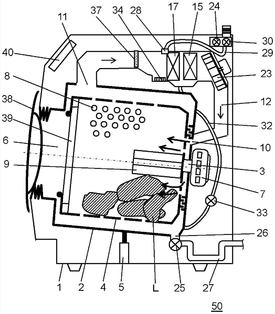
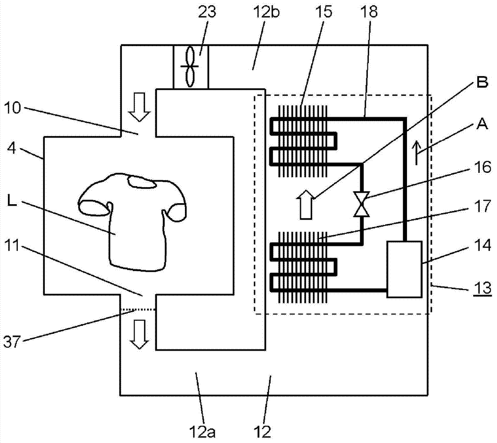
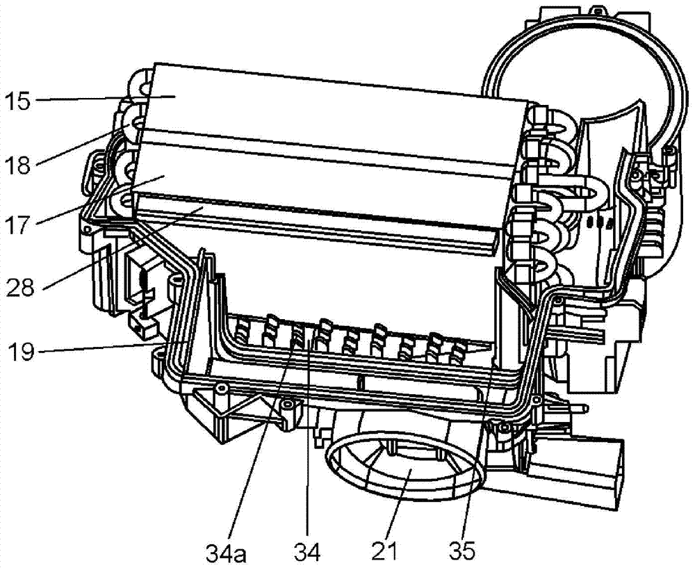
[0033] figure 1 is a diagram schematically showing a cross-sectional structure of clothes dryer 50 according to the first embodiment of the present invention, figure 2 It is a figure showing the schematic structure of the circulation system of the drying air of this clothes dryer 50, image 3 It is a perspective view showing a part of the heat pump device 13 of the clothes dryer 50 . in addition, Figure 4 It is a plan view showing a part of the heat pump device 13 of the clothes dryer 50 according to the first embodiment of the present invention cut away, Figure 5 is a sectional view of main parts of the heat pump device 13, Figure 6 It is a perspective view obtained by cutting a part of the heat pump device 13 and seeing it from below.

[0034] Such as Figure 1 to Figure 6 As shown, the clothes dryer 50 of this embodiment is a so-called washing and drying machine with a washing function...


PUM

PropertyMeasurementUnit
Thicknessaaaaaaaaaa

Abstract

A clothes drying machine (50) provided with a casing (1), a rotating drum (4) rotatably disposed inside the casing (1), and a motor (7) for rotatably driving the rotating drum (4). The clothes drying machine (50) also has a dehumidifier and a heater, and is provided with a drying-air generator for generating air for drying, an air blower for feeding air for drying generated by the drying-air generator into the rotating drum (4), and a circulation air duct (12) for circulating air for drying discharged from the rotating drum (4) back into the rotating drum (4) via the drying-air generator. The clothes drying machine (50) is moreover provided with a case for accommodating the dehumidifier and the heater, a water sprayer for removing foreign matter adhering to the dehumidifier, and a water drainage pathway (32) for discharging water inside the case. The clothes drying machine (50) is furthermore provided with a foreign matter collector (34) for colleting foreign matter removed from the dehumidifier by the water sprayer, wherein the foreign matter collector (34) is arranged below dehumidifier on the upstream side of the flow of air for drying.

Description

technical field [0001] The present invention relates to a clothes dryer and a washing and drying machine for drying clothes and the like. Background technique [0002] In conventional clothes dryers, there is a problem that lint such as lint generated from fiber products such as clothes is mixed with drying air, adheres to the air blower and heat exchanger installed in the circulation air duct, and accumulates, causing the air blower and heat exchange to become unstable. The reason for the degradation of the function of the device. Therefore, a lint filter for trapping lint from the drying air is installed in the circulation duct. [0003] However, since the drying air flowing in the circulation duct needs to ensure a constant air flow rate, the mesh of the lint filter needs to be formed with a certain degree of thickness. Therefore, it is difficult to completely remove the lint from the drying air that has passed through the lint filter, and a part of the lint that has pa...

Claims


Application Information

Patent Timeline
IPC IPC(8): D06F58/02D06F25/00D06F39/08D06F33/54D06F58/38
CPCD06F58/206D06F58/22D06F25/00D06F58/24D06F33/54D06F2105/02D06F58/38D06F2103/04D06F2103/32D06F2103/08D06F2105/62
Inventor 河合雅弘田原己纪夫藤原宣彦中井厚仁桐山博之
Owner PANASONIC INTELLECTUAL PROPERTY MANAGEMENT CO LTD
Why Eureka
Eureka Blog
Learn More