Connector

A technology of connectors and housings, which is applied in the direction of connections, parts of connection devices, devices for preventing wrong connections, etc., can solve problems such as large-scale and complex structures, and achieve the effect of ensuring smoothness

Active Publication Date: 2015-04-15
SUMITOMO WIRING SYST LTD
View PDF6 Cites 8 Cited by
  • Summary
  • Abstract
  • Description
  • Claims
  • Application Information

AI Technical Summary

Problems solved by technology

In view of this problem, if a structure that prevents the detection part from being locked and released is newly provided on the housing, it will lead to an increase in size and complexity of the structure, which will cause undesirable problems.

Method used


Image

  • Connector
  • Connector
  • Connector

Examples


Embodiment 1

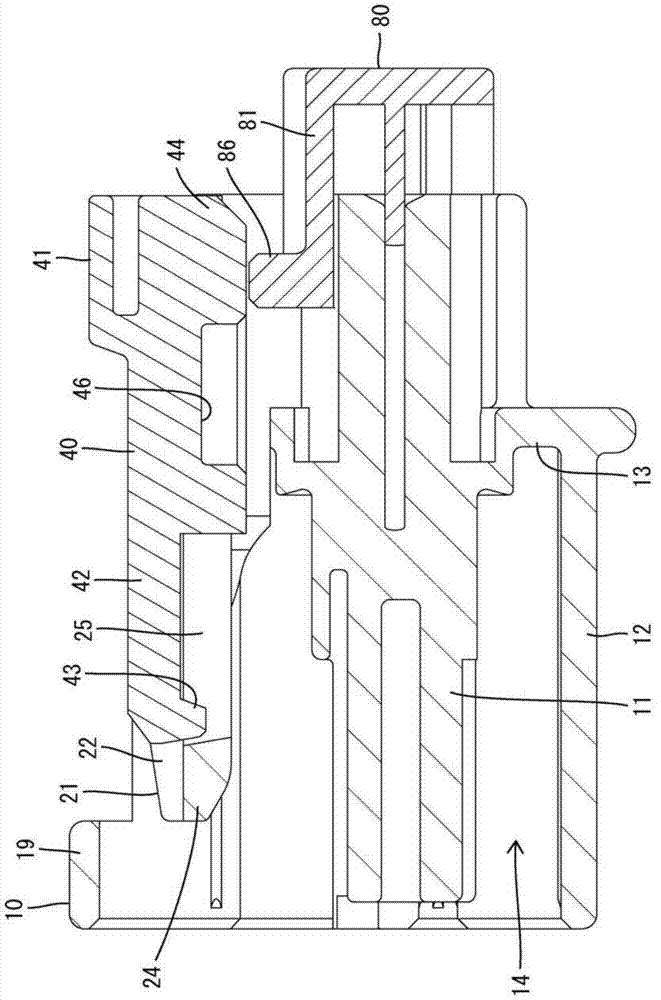
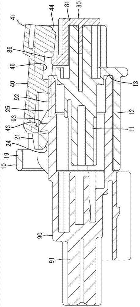
[0029] pass Figure 1 to Figure 13 Example 1 of the present invention will be described. The connector of Embodiment 1 has a housing 10, a detection member 40, and a holder 80 as a mounting member. The case 10 can be fitted with the mating case 90 . In addition, in the following description, with respect to the front-rear direction, the one surface side of the case 10 and the mating case 90 facing each other at the start of fitting is referred to as the front, and as the up-down direction, Figure 1 ~ Figure 3 as a benchmark.

[0030] Such as figure 2 As shown, the counterpart housing 90 is made of synthetic resin and has a block-shaped terminal accommodating portion 91 and a cylindrical cover portion 92 protruding forward from the front end outer peripheral edge of the terminal accommodating portion 91 . A lock protrusion 93 protrudes from the upper surface of the cover portion 92 . A mating terminal fitting (not shown) can be accommodated in the terminal accommodating ...


PUM


Abstract

The invention discloses a connector which can prevent a detection component from moving freely on the basis of avoiding large size and complexity of a housing. The detection component (40) can be assembled to the housing (10) in the manner of moving between an initial position and a detection position. The detection component is bent and deformed in the process of moving from the initial position to the detection position, and elastically reset in the detection position and maintain the state that the return movement to the initial position with respect to a locking arm (21) is limited. A retainer (80) is installed on the housing. A limiting part (86) is disposed on the retainer. In a state of being correctly installed to the housing, the limiting part (86) is configured in a position corresponding to a retreat part (46) of the detection component in the process when the detection component moves to the detection position from the initial position so as to allow bending of the detection component, and is configured in a position to be withdrawn from the retreat part when the detection component arrives the detection position so as to limit the bending of the detection component.

Description

technical field [0001] The invention relates to a connector. Background technique [0002] The connector disclosed in Patent Document 1 includes: a housing having a bendable lock arm; and a detection member assembled to the housing so as to be movable between a standby position (initial position) and a detection position. The housing can be fitted with the counterpart housing, and when correctly fitted, the locking arm is elastically locked to the locking protrusion of the counterpart housing, thereby keeping the two housings in a mated state. In addition, the detection member abuts against the rear surface of the stopper of the lock arm during the fitting process of the two housings, thereby being restricted from moving to the detection position, and is locked by the locking protrusion of the opposite housing when the two housings are correctly fitted. The abutting state with the lock arm is released, allowing movement to the detection position. And, in the detection posi...

Claims


Application Information

Patent Timeline
IPC IPC(8): H01R13/64H01R13/639
CPCH01R13/641
Inventor 郑松
Owner SUMITOMO WIRING SYST LTD
Why Eureka
Try Eureka