Varifocal reflecting surface system based on rib column cable network structure

A technology of cable net structure and reflective surface, which is applied in the field of communication and electronics, can solve the problems of high cost, low utilization efficiency of reflective surface, limited transmission range of electromagnetic energy or light energy, etc., to achieve precise focus adjustment, convenient adjustment, The effect of high surface accuracy

Active Publication Date: 2015-04-15
XIDIAN UNIV
View PDF4 Cites 10 Cited by
  • Summary
  • Abstract
  • Description
  • Claims
  • Application Information

AI Technical Summary

Problems solved by technology

However, the large-scale zoom function is still difficult to achieve
[0007] The reflective surface with a fixed solid surface is used. Since the feed source position of the antenna is fixed, it can only receive or reflect the feed source at a fixed position, and it is impossible to share the same reflective surface with multiple feed sources. The

Method used


Image

  • Varifocal reflecting surface system based on rib column cable network structure
  • Varifocal reflecting surface system based on rib column cable network structure
  • Varifocal reflecting surface system based on rib column cable network structure

Examples


Embodiment 1

[0039] Embodiment 1: A ring rib column cable net reflective surface system using a zoom sleeve.

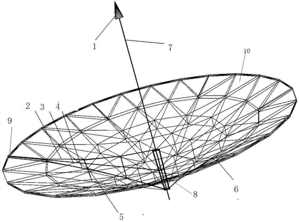
[0040] refer to figure 1 with figure 2 , the present invention includes: feed source 1, reflection cable net 2, support rib structure 3, support cable net 4, vertical stay cable 5, ring fixed truss structure 6, center pole 7, zoom sleeve 8, ring rib Joint 9 and reflective surface 10. Among them: the zoom sleeve 8 is set outside the center pole 7, the feed source 1 is installed on the top of the center pole 7; one end of the supporting rib structure 3 is connected with the ring-shaped fixed truss structure 6 through the ring rib joint 9, and the other end is connected with the The middle part of the zoom sleeve 8 is connected to form a rigid overall structure; one end of the reflection cable net 2 is connected to the upper end of the annular fixed truss structure 6, and the other end is connected to the upper end of the zoom sleeve 8; one end of the support cable net 4 is connec...

Embodiment 2

[0046] Example 2: Ring Rib Column Cable Net Reflecting Surface System Using Up and Down Moving Sleeves

[0047] refer to image 3 with Figure 4 , the present invention includes: feed source 1, reflective cable net 2, supporting rib structure 3, supporting cable net 4, vertical stay cable 5, annular fixed truss structure 6, central pole 7, ring rib joint 9, reflecting surface 10 , upper moving sleeve 11, lower moving sleeve 12, upper cable regulator 13, lower cable regulator 14 and rotating straight rod 15; upper cable regulator 13, upper moving sleeve 11, lower cable regulator 14 and The lower moving sleeve 12 is sequentially set on the outside of the central pole 7, and the feed source 1 is installed on the top of the central pole 7; one end of the supporting rib structure 3 is connected with the annular fixed truss structure 6 through the ring rib joint 9, and the other end is connected with the The lower moving sleeve 12 is connected; one end of the rotating straight rod...


PUM

PropertyMeasurementUnit
Caliberaaaaaaaaaa
Outer diameteraaaaaaaaaa
The inside diameter ofaaaaaaaaaa

Abstract

The invention discloses a varifocal reflecting surface system based on a rib column cable network structure, and mainly aims to solve the problems that the focus of a conventional surface cannot be varied and the feed source position is fixed. The varifocal reflecting surface system comprises a feed source (1), a reflecting cable network (2), a support rib rod structure (3), a support cable network (4), vertical pull ropes (5), an annular fixing truss structure (6), a central support rod (7), annular rib joints (9) and a reflecting surface (10), wherein a varifocal sleeve (8) sleeves the outer side of the central support rod (7); the varifocal sleeve (8) is connected with the reflecting cable network (2) and the support cable network (4); the position of the varifocal sleeve (8) is adjusted to change the lengths of the reflecting cable network (2) and the support cable network (4), so that large-scale focus variation that the shape of the reflecting surface (10) transits to a plane from a parabolic plane is achieved. The varifocal reflecting surface system is simple, convenient and flexible in structure, the focus range and the reflection function of the reflecting surface are expanded, and the varifocal reflecting surface system can be applied to convergence or reflection of electromagnetic waves or optical energy of outer space, war ships or the ground.

Description

technical field [0001] The invention belongs to the technical field of communication and electronics, in particular to a variable focal length reflecting surface system, which can be used for converging or reflecting electromagnetic waves or light energy in space, ships or ground. Background technique [0002] Zoom technology is widely used in optical systems. For example, in the lens of a camera, the focal length can be appropriately changed by rotating the focus ring of the lens to achieve a change in the focusing distance, thereby completing clear shooting of objects at different distances. [0003] However, in the large-scale reflector system commonly used in the field of communication and electronic technology, there are few reports on the zoom application. The reasons can be summarized as follows: [0004] For a small-sized reflector system, the zoom range and power are limited, so the application significance is not great. [0005] For large-scale deployable reflect...

Claims


Application Information

Patent Timeline
IPC IPC(8): H01Q15/14H01Q15/16
Inventor 郑飞陈梅谭谋
Owner XIDIAN UNIV
Why Eureka
Try Eureka